Difference between revisions of "Chapter Four: Off-Site Sanitation Systems"
| Line 271: | Line 271: | ||
[[File:Section_View_of_a_Grease_Trap.png|600px|link=Chapter_Four:_Off-Site_Sanitation_Systems#Grease_Trap]]<br> | [[File:Section_View_of_a_Grease_Trap.png|600px|link=Chapter_Four:_Off-Site_Sanitation_Systems#Grease_Trap]]<br> | ||
Figure 4.35: Section View of a Grease Trap (Source: Tilley et al., 2014) | Figure 4.35: Section View of a Grease Trap (Source: Tilley et al., 2014) | ||
| + | |||
====Design Considerations for Grease Trap==== | ====Design Considerations for Grease Trap==== | ||
The minimum requirements for grease trap design are:<br> | The minimum requirements for grease trap design are:<br> | ||
Revision as of 00:24, 15 July 2022
Contents
- 1 Chapter Four: Off-site Sanitation Systems
1 Chapter Four: Off-site Sanitation Systems
Off-site sanitation refers to a sanitation system in which wastewater and excreta are collected and conveyed away from the plot where they are generated. An off-site sanitation system relies on a sewer technology (simplified sewer, solid free sewer or conventional sewer) for conveyance of excreta.
1.1 Decentralized Wastewater Treatment Systems (DEWATS)
Decentralized wastewater management systems (DEWATS) include all parts of a onsite-sanitation system. In comparison to centralized systems, these systems are located at or near the point of wastewater generation. DEWATS can be characterized and differentiated from centralized systems along the following lines.
- Volume: Decentralized systems treat relatively small volumes of water (typically 1-1,000 m³/day),
- Sewer type: Centralized systems typically use conventional gravity sewers, while decentralized systems typically use small-diameter gravity sewers, often employing intermediate settlers for solid-free sewers.
1.2 Components of DEWATS
The components of DEWATS are presented in the schematic layout shown in Figure 4.1
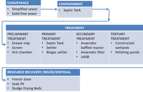
Figure 4.27: Treatment Flow Sheet for Components of DEWATS (Source: MoW, 2018)
1.2.1 Containment
Containment technologies collect and store wastewater at the user interface on-site. Containment technologies are usually applicable for low-cost, non-sewered sanitation (FS) systems as intermediate storage, but can also serve as pre-treatment modules for small-scale wastewater treatment systems. The main containment technology applicable for wastewater treatment technologies is a septic tank (see Figure 4 .28).
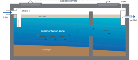
Figure 4.28: The Cross Section of a Septic Tank
(Source: MoW, 2018)
In the vast majority of situations, containment systems are already installed on-site but are often improperly designed, constructed and maintained, which poses severe environmental hazards. Apart from septic tanks providing some degree of pre-treatment, the effluent usually contains high concentrations of pollutants, which can carry severe public health and environmental burdens, especially in densely populated urban areas and in the vicinity of drinking water sources. Hence, proper sealing of containment options is crucial for environmental sanitation. Containment systems can also be implemented to buffer peak flows.
1.2.2 Design of Septic Tank
The capacity of septic tank depends on number of users and interval of sludge removal. Normally sludge should be removed every 2 years. The liquid capacity of the tank is taken as 130 litres to 70 litres per head. For small number of users 130 litres per head is sufficient.
A septic tank is usually provided with brick walls in which cement mortar [not less than 20 cm (9 inch)] thick and the foundation floor is of cement concrete 1:2:4. Both inside and outside faces of the wall and top of the floor are plastered with minimum thickness of 12mm thick cement mortar 1:3 mix.
All inside corners of the septic tank are rounded. Water proofing agent (such as Impermo, Cem-seal or Accoproof, etc.) is added to the mortar at the rate of 2% of the cement weight. Water proofing agent is to be added in similar proportion in to the concrete also for making the floor of the tank.
For proper convenience in collection and removal of the sludge, the floor of the septic tank is given a slope of 1:10 to 1:20 towards the inlet side. Which means that the floor of the outlet side will be on the higher elevation than the floor at the inlet side.
1.2.2.1 Dimensioning a Septic Tank
(A) Length, Width and Depth of Septic Tank
Width = 750 mm (minimum)
Length = 2 to 4 times width
Depth = 1,000 to 1,300 mm. (min below water level) + 300 to 450 mm free board
Maximum depth = 1,800 mm + 450 mm free board
Capacity = 1 cubic metre (minimum)
(B) Detention period
Detention period of 24hrs (is mostly) considered in septic tank design. The rate of flow of effluent must be equal to the rate of flow of the influent.
(C) Inlet and outlet pipes
An elbow or T pipe of 100mm diameter is submerged to a depth of 250-600 mm below the liquid level. For the outlet pipe an elbow or T type of 100mm diameter pipe is submerged to a depth of 200-500 mm below the liquid level. Pipes may be of stone ware or asbestos or PVC.
(D) Baffle Walls of the Septic Tank
For small tanks, RCC hanging type scum baffle walls are provided in septic tanks. Baffle walls are provided near the inlet. It is optional near the outlet. The inlet baffle wall is placed at a distance of L/5 from the wall, where L is the length of the wall. The baffle wall is generally extended 150 mm above to scum level and 400-700 mm below it.
Scum being light, generally floats at the water level in the tank. Thickness of the wall varies from 50 mm to 100 mm. For large tanks the lower portion has holes for flow of sludge.
(E) Roofing Slab of the Septic Tank
The top of the septic tank is covered with a RCC slab of thickness of 75-100 mm depending upon the size of the tank. Circular manholes of 500mm clear diameter are provided for inspection and desludging. In case of rectangular opening clear size is kept as 600 x 450 mm.
(F) Ventilation Pipe
For outlet of foul gases and ventilation purpose cast iron or asbestos pipe of 50-100 mm diameter is provided which should extend 2m (minimum) above ground level. Top of the ventilation pipe is provided with a mosquito proof wire mesh or cowl.
1.2.3 Conveyance
Technologies presented in this section are sewer-based technologies, using water from waterborne toilets as a conveying medium.
1.2.3.1 Simplified Sewer
A simplified sewer describes a sewerage network that is constructed using smaller diameter pipes laid at a shallower depth and at a flatter gradient than conventional sewers (Figure 4.3).
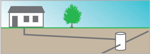
Figure 4.29: Sketch of a Simplified Sewer
(Source: MoW, 2018)
This sewer system generally does not apply pumping. For this reason, a simplified sewer allows for a more flexible design at lower cost. Simplified sewers can be installed in almost all types of settlements and are especially appropriate for densely populated urban areas where space for on-site technologies is limited. The sewers should be considered as an option where there is significant population density (about 150 inhabitants per hectare) and a reliable water supply system (at least 60 L/capita/day).
1.2.3.1.1 Design considerations for simplified sewers
In contrast to conventional sewers that are designed to ensure a minimum self-cleansing velocity, the design of simplified sewers is based on a minimum tractive tension of 1 N/m2 (1 Pa) at peak flow. The minimum peak flow should be 1.5 L/s and a minimum sewer diameter of 100 mm is required. A gradient of 0.5% is usually sufficient. For example, a 100 mm sewer laid at a gradient of 1m in 200 m will serve around 2,800 users with a wastewater flow of 60 L/person/day. PVC pipes are recommended for use. The depth at which they should be laid depends mainly on the amount of traffic. Below sidewalks, soil covers of 40 to 65 cm are typical. The simplified design can also be applied to sewer mains. They can also be laid at a shallow depth, provided that they are placed away from traffic.
Expensive manholes are normally not needed. At each junction or change in direction, simple inspection chambers (or cleanouts) are provided as can be seen on Figure 4 .29. Inspection boxes are also used at each house connection. Where kitchen grey water contains an appreciable amount of oil and grease. The installation of grease traps is recommended to prevent clogging. Grey water should be discharged into the sewer to ensure adequate hydraulic loading, but storm water connections should be discouraged. In practice it is difficult to exclude all storm water flows, especially where there is no alternative for storm drainage. The design of sewers (and treatment plants) should, therefore, take into account the extra flow that may result from storm water inflows.
1.2.3.1.2 Design Procedures for Simplified Sewers
Step 1. Estimation of the wastewater flow
Daily peak flows
The value of the wastewater flow used for sewer design is the daily peak flow. This can be estimated as follows:
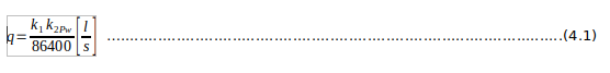
where: q = daily peak flow, l/s k1 = peak factor (=daily peak flow divided by average daily flow) k2 = return factor (=wastewater flow divided by water consumption) P = population served by length of sewer under consideration w = average water consumption, litres per person per day and 86,400 is the number of seconds in a day.
A suitable design value for k1 for simplified sewerage is 1.8 and k2 may be taken as 0.85.
Thus, equation 4.1 becomes:
![]()
Variations in the value of k2 have a much lower impact on design, except in middle and high-income areas where a large proportion of water consumption is also for lawn-watering and car-washing. In peri-urban areas in Brazil a k2 value of 0.85 has been used successfully, although other counties use a value of 0.65, even in low income areas and without any reported operational problems (Luduvice, 2000). However higher values may be more appropriate elsewhere–for example, in areas where the water supply is based on a system of public standpipes, values up to 0.95 may be used.
Step 2. Sizing of a simplified sewer
The flow in simplified sewers is always assumed to be an open channel flow–that is to say, there is always some free space above the flow of wastewater in the sewer. The hydraulic design of simplified sewers requires knowledge of the area of flow and the hydraulic radius. Both these parameters vary with the depth of flow.
From Figure 4 .30 shows the trigonometric relationships which can be derived for the following parameters:
(i) The area of flow(a), expressed in m2;
(ii) The wetted perimeter(p), m;
(iii) The hydraulic radius(r), m; and
(iv) The breadth of flow (b), m.
The hydraulic radius (sometimes called the hydraulic mean depth) is the area of flow divided by the wetted perimeter.
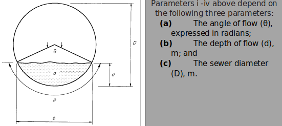
Figure 4.30: Definition of Parameters for Open Channel Flow in a Circular Sewer (Source: Mara, 1996)
If the angle of flow is measured in degrees, it must be converted to radians by multiplying by (2π/360), since 360o equals 2π radians.
The ratio d/D is termed the proportional depth of flow (which is dimensionless). In simplified sewerage systems the usual limits for d/D are as follows:
0.2 <d/D < 0.8
The lower limit ensures that there is sufficient velocity of flow to prevent solids deposition in the initial part of the design period, and the upper limit provides for sufficient ventilation at the end of the design period. The equations are as follows:
Angle of flow, θ = 2 cos-1 [1 – 2 (d/D)] .....................................................................(4.3)
Area of flow, a = D2 [(θ – sin θ) / 8] ..........................................................................(4.4)
Wetted perimeter, p = θ D/2 .....................................................................................(4.5)
Hydraulic radius (= a/p), r = (D/4) [1 – ((sin θ) /θ)]....................................................(4.6)
Breadth of flow, b = D sin (θ/2), ................................................................................(4.7)
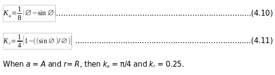
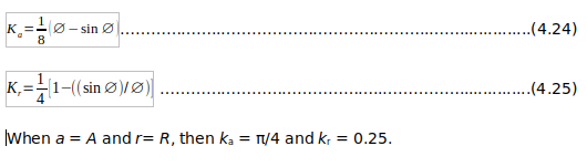
When d = D (that is, when the sewer is flowing just flow), then a = A = π D2/4; p = P = πD and r = R = D/4.
The following equations for ‘’a’’ and ‘’r’’ are used in designing simplified sewers:
a =kaD .......................................................................................................................(4.8)
r = krD .......................................................................................................................(4.9)
.
The coefficients ka and kr are given from equations 4.8 and 4.9 as:
Step 3. Velocity of flow In 1889, Robert Manning (an Irish civil engineer, 1816-1897) presented his formula relating to the velocity of flow in a sewer to the sewer gradient and the hydraulic radius (Manning, 1890). The formula is commonly, but improperly, known as the Manning equation; as pointed out by Williams (1970) and Chanson (1999). it should be known as the Gauckler-Manning equation since Philippe Gauckler (a French civil engineer,1826-1905) published the same equation 4.12 years earlier (Gauckler, 1867 and1868).
The Gauckler-Manning equation is
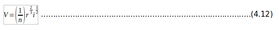
Where
V = velocity of flow at d/D, m/s
n = Ganguillet-Kutter roughness coefficient, dimensionless
r = hydraulic radius at d/D, m
i = sewer gradient, m/m (i.e. dimensionless)
Since flow = area × velocity
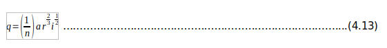
Where q = flow in sewer at d/D, m3/s
Using equations 4.8 and 4.9, equation 4.14 becomes:
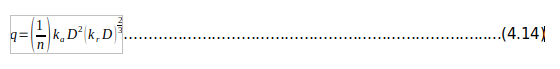
The usual design value of the Ganguillet - Kutter roughness coefficient, n is 0.013. This value is used for any relatively smooth sewer pipe material (concrete, PVC or vitrified clay) as it depends not so much on the roughness of the material itself, but on the roughness of the bacterial slime layer which grows on the sewer wall.
1.2.3.2 Solids-free Sewer
Solids-free sewers are also referred to as settled, small-bore, variable-grade gravity, or septic tank effluent gravity sewers. A precondition for solids-free sewers is efficient primary treatment at the household level. Figure 4 .31 presents section of solids free sewers.
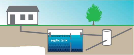
Figure 4.31: Section of Solids Free Sewers (Source: Tilleyet al., 2014)
An interceptor, typically a single-chamber septic tank, captures settleable particles that could clog small pipes. The solids interceptor also functions to attenuate peak discharges. Because there is little risk of depositions and clogging, solids-free sewers do not have to be self-cleansing, i.e., no minimum flow velocity or tractive tension is needed. They require few inspection points, can have inflective gradients (i.e., negative slopes) and follow the topography. When the sewer roughly follows the ground contours, the flow is allowed to vary between open channel and pressure (full-bore) flow.
1.2.3.2.1 Design Considerations for Solid Free Sewers
If the interceptors are correctly designed and operated, this type of sewer does not require self-cleansing velocities or minimum slopes. Even inflective gradients are possible, as long as the downstream end of the sewer is lower than the upstream end. Solids-free sewers do not have to be installed on a uniform gradient with a straight alignment between inspection points. The alignment may curve to avoid obstacles, allowing for greater construction tolerance. At high points in sections with pressure flow, the pipes must be ventilated. A minimum diameter of 75 mm is required to facilitate cleaning.
Expensive manholes are not needed because access for mechanical cleaning equipment is not necessary. Cleanouts or flushing points are sufficient and are installed at upstream ends, high points, intersections, or major changes in direction or pipe size. Compared to manholes, cleanouts can be more tightly sealed to prevent storm water from entering. Storm water must be excluded as it could exceed pipe capacity and lead to blockages due to grit depositions. Ideally, there should not be any storm- and groundwater in the sewers, but, in practice, some imperfectly sealed pipe joints must be expected. Estimates of groundwater infiltration and storm water inflow must, therefore, be made when designing the system. The use of PVC pipes can minimize the risk of leakages.
1.2.3.2.2 Design Steps for Solids Free Sewers
A similar equation to simplified sewers can be used to design the size of a sewer in case of very large flow rate of the wastewater. The design of solids free sewers follows the following steps:
Step 1. Estimation of the waste water flow
Daily peak flows
The value of the wastewater flow used for sewer design is the daily peak flow. This can be estimated as follows:
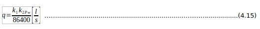
where
q = daily peak flow, l/s k1 = peak factor (=daily peak flow divided by average daily flow) k2 = return factor (=wastewater flow divided by water consumption) P = population served by length of sewer under consideration w = average water consumption, litres per person per day and 86,400 is the number of seconds in a day
A suitable design value for k1 for simplified sewerage is 1.8 and k2 may be taken as 0.85.
Thus, equation 4.1 becomes;
q = 1.8 × 10⁻⁵P………………...........................................................................…...…(4.16)
Variations in the value of k2 have a much lower impact on design, except in middle and high-income areas where a large proportion of water consumption is used for lawn-watering and car-washing. In peri-urban areas in Brazil a k2 value of 0.85 has been used successfully, although other countries use a value of 0.65, even in low income areas and without any reported operational problems (Luduvice, 2,000). However higher values may be more appropriate elsewhere – for example, in areas where the water supply is based on a system of public standpipes, values up to 0.95 may be used.
Step 2: Sizing of conventional gravity sewers
The flow in simplified sewers is always assumed to be an open channel flow–that is to say, there is always some free space above the flow of wastewater in the sewer. The hydraulic design of conventional gravity sewers requires knowledge of the area of flow and the hydraulic radius. Both these parameters vary with the depth of flow. From figure below trigonometric relationships can be derived for the following parameters:
(a) The area of flow (a), expressed in m2;
(b) The wetted perimeter(p), m;
(c) The hydraulic radius (r), m; and
(d) The breadth of flow (b), m.
The hydraulic radius (sometimes called the hydraulic mean depth) is the area of flow divided by the wetted perimeter.
Figure 4.32: Definition of Parameters for Open Channel Flow in a Circular Sewer
(Source: Mara, 1996)
If the angle of flow is measured in degrees, then it must be converted to radians by multiplying by (2π/360), since 360o equals 2π radians. The ratio d/D is termed the proportional depth of flow (which is dimensionless). In simplified sewerage pipes the usual limits for d/D are as follows:
0.2 <d/D < 0.8
The lower limit ensures that there is sufficient velocity of flow to prevent solids deposition in the initial part of the design period, and the upper limit provides for sufficient ventilation at the end of the design period. The equations are as follows:
Angle of flow, θ = 2 cos-1 [1 – 2 (d/D)]………………….....…………..…......(4.17)
Area of flow, a = D2 [(θ – sin θ) / 8].....……..………………………...……….(4.18)
Wetted perimeter, p = θ D/2.........……………………………...…..................(4.19)
Hydraulic radius (= a/p), r = (D/4) [1 – ((sin θ) /θ)].....………….………........(4.20)
Breadth of flow, b = D sin (θ/2)......………………………………..……..……..(4.21)
When d = D (that is, when the sewer is flowing just flow), then a = A = π D2/4; p = P = πD and r = R = D/4.
The following equations for ‘’a’’ and ‘’r’’ are used in designing simplified sewers:
a = kaD2 ………………………………………………………………….........................(4.22)
r = krD……………………………….………………………..…………..........................(4.23)
The coefficients ka and kr are given from equations 4.22 and 4.23 as:
1.2.3.3 Conventional Gravity Sewer
Conventional gravity sewers are large networks of underground pipes that convey backwater, grey water and, in many cases, storm water from individual households to a (semi-)centralised treatment facility using gravity (and pumps when necessary). Schematic layout sketch of a conventional gravity sewer is presented in Figure 4 .33.
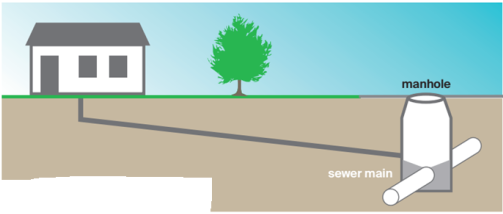
Figure 4.33: Schematic Layout Sketch of a Conventional Gravity Sewer
(Source: MoW, 2018)
Since they can be designed to carry large volumes, conventional gravity sewers are very appropriate to transport wastewater to a (semi-) centralised treatment facility. The construction of conventional sewer systems in dense, urban areas is complicated because it disrupts urban activities and traffic. Conventional gravity sewers are expensive to build and a professional management system must be in place, as the installation of a sewer line is disruptive and requires extensive coordination between related authorities, construction companies and property owners.
1.2.3.3.1 Design Considerations
Conventional gravity sewers normally do not require on-site pre-treatment, primary treatment or storage of the household wastewater before it is discharged. The sewer must be designed, however, such that it maintains self-cleansing velocity (i.e., a flow that will not allow particles to accumulate). For typical sewer diameter s, a minimum velocity of 0.6 to 0.7 m/s during peak dry weather conditions should be adopted. A constant downhill gradient must be guaranteed along the length of the sewer to maintain self-cleansing flows, which can require deep excavations. When a downhill grade cannot be maintained, a manhole must be installed. Primary sewers are laid beneath roads, at depths of 1.5 to 3 m to avoid damages caused by traffic loads. The depth also depends on the groundwater table, the lowest point to be served (e.g., a basement) and the topography. The selection of the pipe diameter depends on the projected average and peak flows. Commonly used materials are concrete, PVC, and ductile or cast iron pipes.
Access manholes are placed at set intervals above the sewer, at pipe intersections and at changes in pipeline direction (vertically and horizontally). Manholes should be designed such that they do not become a source of storm water inflow or groundwater infiltration.
1.2.3.3.2 Design Steps for Conventional Gravity Sewers
The design steps for the conventional gravity sewers should be the same as those for simplified and solids free sewers. In addition, the design for the system should allow for weir for discharge measurements. Please refer to these sections for the design of conventional gravity sewers. For conventional gravity sewer lines, the following should be observed on the pipe sizes to be applied because of potential abuse by users by introducing solids into the sewer lines:
(a) Any new sewer connection should use plastic pipes of diameter not less than 150 mm or (6") for further extensions (limited number of connected customers not more than 5 in number for domestic use only). (b) Lateral sewers, incorporating more than 5 sewer connections and that may need further extensions in future should involve plastic pipes of diameter not less than 200 mm or (8"). (c) Commercial and public sewer connections at lodges, hotels, business centres, institutions, industries, apartments and others should use plastic pipes of not less than 200 mm (8"). (d) All main sewers should start with pipes not less than 200 mm (8").
Note that: The previously designed plastic pipes of more than 500 mm were discouraged to provide room for concrete pipes from that diameter. From field practical experience concrete pipes have higher roughness than plastic pipes and are easily corroded by sewage. Plastic pipes of various diameters and appurtenances for application in sewerage lines are currently manufactured and available in Tanzania.
1.2.4 Wastewater Treatment
Wastewater treatment is a process used to remove contaminants from wastewater or sewage and convert it into an effluent that can be returned to the water cycle with minimum impact on the environment, or directly reused (https://en.wikipedia.org/wiki/Wastewater_treatment). The typical wastewater treatment flow sheet is presented Figure 4 .34.
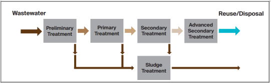
Figure 4.34: A Typical Flow Sheet for a Wastewater Treatment Plant
(Source: MoW, 2018)
1.2.5 Preliminary Treatment
1.2.5.1 Grease Trap
Fats, oils and grease are a major component of human food stuffs. The term 'grease' is commonly used and sometimes includes the fats, oils, waxes, and other related constituents found in waste water. Greases are solid products (as long as the temperature is sufficiently low) of animal or vegetable origin present in municipal waste water and in some industrial waste waters.
At municipal and industrial wastewater treatment plants where large quantities of grease and fat are to be removed, both aided and induced flotation systems are used to separate the grease and fat from the sewage. These systems involve the use of gas (normally air) bubbles to promote the separation of fat and grease particles from the liquid medium in which they are carried. The rising velocity of the gas bubble determines the efficiency of removal of grease and fat. shows section view of a grease trap. The rising velocity of the gas bubble This is sometimes calculated from Stokes equation which is as follows:
Stokes Equation
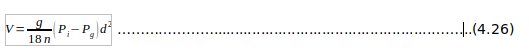
Where:
V = the rising velocity;
d = diameter of air bubbles;
Pg = density of the gas;
Pi= density of the liquid:
n= absolute viscosity; and
g = gravitational acceleration
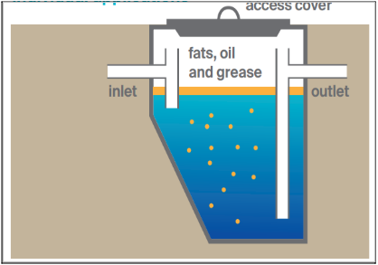
Figure 4.35: Section View of a Grease Trap (Source: Tilley et al., 2014)
1.2.5.2 Design Considerations for Grease Trap
The minimum requirements for grease trap design are:
(a) Provision of sufficient capacity to slowdown the passing wastewater, giving greasy waste, the opportunity to separate out. Check the size of an existing grease trap or determine the approximate size of a new grease trap.
(b) The length of the trap should be equal to between 1.3 and 2.0 times the total depth. Note that usually, the grease trap contents occupy 2/3 of the total depth; the top 1/3 of the trap is head space. Do not include wall and cover thickness in the length and depth measurements if the grease trap is built of concrete.
(c) The surface area of the trap (the length times the width in square millimetres) should be equal to between 1,000 and 2,000 times the total depth measured in millimetres. Again, do not include wall and cover thickness in measuring a concrete trap.
(d) Prevent wastewater entering the grease trap from mixing up the top greasy waste layer. A baffle should be present at the trap inlet to slow down the incoming wastewater and keep it separate from the top waste layer. The inlet pipe should end in a 90° downwards bend so that incoming wastewater enters the trap at least 100 mm below the water surface. The inlet pipe should not terminate above the liquid surface such that wastewater drops into the trap.
(e) Allow access to the trap for maintenance so that all covers can be lifted and accumulated material removed from both the top and bottom of the trap. Except for very large grease traps, the total depth of liquid should never exceed 1200 mm. A sampling hole with an appropriate cover must also be provided if the opening for maintenance access does not also give access to the grease trap outlet.
(f) Provide necessary safety features. All grease traps must be vented. Under-floor grease traps and grease traps with over 1000 litre capacity must be provided with a prominent sign to show location, to indicate both total and liquid depth, and the maximum allowable thickness of the greasy waste layer (30%).
1.2.5.3 Screens
Screening is the first unit operation used at wastewater treatment plants (WWTPs). Screening removes objects such as rags, paper, plastics, and metals to prevent damage and clogging of downstream equipment, piping, and appurtenances. Some modern wastewater treatment plants use both coarse screens and fine screens.
(a) Coarse Screens
Coarse screens remove large solids, rags, and debris from wastewater, and typically have openings of 6 mm (0.25 in) or larger. Types of coarse screens include mechanically and manually cleaned bar screens, including trash racks. Table 4.1 provide a description of wastewater screen types.
Table 4.25: Description of Coarse Screens
| Screen Type | Description |
|---|---|
| Trash rack | Designed to prevent logs, timbers, stumps, and other large debris from entering treatment processes.
Opening size: 38 to 150 mm |
| Manually cleaned bar screen | Designed to remove large solids, rags, and debris.
Opening size: 30 to 50 mm Bars are set at 30 to 45 degrees from vertical to facilitate cleaning. Primarily used in older or smaller treatment facilities, or in bypass channels |
| Mechanically cleaned bar screen | Designed to remove large solids, rags, and debris.
Opening size: 6 to 38 mm. Bars are set at 0 to 30 degrees from vertical. Almost always used in new installations because of a large number of advantages relative to other screens. |
(b) Fine Screens
Fine screens are typically used to remove material that may create operation and maintenance problems in downstream processes, particularly in systems that lack primary treatment. Typical opening sizes for fine screens are 1.5 to 6 mm. Very fine screens with openings of 0.2 to 1.5 mm placed after coarse or fine screens can reduce suspended solids to levels near those achieved by primary clarification.
(c) Screen Design Steps
Step 1: Selection
The specific screen to be selected will depend on the application. In general, the approach as set out in Table 4 .26is suggested.
Table 4.26: Screen Selection
| Application | Aperture | Type |
|---|---|---|
| Large Pump houses | 50 - 15 mm | Trash rack R.B.I. |
| Small Pump houses | 50 mm | Liftable cage Bar screen |
| Small Wastewater Treatment Plants (Without Sludge Treatment) | 15 - 25 mm | Curved bar screen Vertical bar screen Inclined bar screen |
| Small Wastewater Treatment Plant (With Sludge Treatment) | 5 - 10 mm | Inclined bar screen Vertical bar screen Band screen |
| Medium Wastewater Treatment Plant (With Sludge Treatment) | 5 - 10 mm | Inclined bar screen Vertical bar screen Band screen Screezer (V.D.S.) Rotomat Contra-shear |
| Large Wastewater Treatment Plants (With Sludge Treatment) | 15 - 50mm (Before Fine Screen) | Vertical bar screen |
| 5 - 10 mm | Band screen Drum screen Cup screen. Screezer (V.D.S.) Rotomat. Contra-shear | |
| Overflows (Retain Screenings in Foul Flow) | 5 - 10 mm | Discreen J&A Weir Mount |
(Source: Clay et al., 1996)
(d) Design Factor for Screens
The basic design of a bar screen should be such that the velocity through the screen would he sufficient for matter to attach itself to the screen without producing an excessive loss of head or complete clogging of the bars. At the same time, velocities in the channel upstream should be sufficient to avoid deposition of solids. In all cases the shape of the bar should be tapered from the upstream side so that any solids which pass the upstream face of the screen cannot be jammed in the screen, thereby causing a trip out of the raking mechanism. Table 4 .27 gives the design factors for bar screens:
Table 4.27: Bar Screen Design Factors
| Item | Manually cleaned | Mechanically cleaned |
|---|---|---|
| Bar Size: Width (mm) Depth (mm) |
5 - 15 25 - 80 |
5- 15 25 - 80 |
| Aperture (mm) | 20 - 50 | 5 - 80 |
| Slope to Flow (Deg) | 450 - 600 | 180 - 900 |
| Velocity Through Screen (m/s) | 0.3 - 0.6 | 0.6 - 1.0 (Max. 1.4) |
(Source: Clay et al., 1996)
The following equations may be used for standard bar screens to calculate the width of channel required and the head loss through the screen:
Width of Channel, W can be calculated as follows;
File:Equation10.png
Where Q = Maximum Flow (m3Is) V = Velocity Through Screen (mis) v = Velocity in Upstream Channel (m/s) D = Depth of Flow (m) W = Width of Channel (m) S = % Screen Open Area. HL = Head Loss Through Screen (m) g = 9.81 m/s2 (gravity). h = Head on Screen Upstream (m) A = Submerged Aperture Area (mm2) B = Bar Width (mm) ɵ = Angle of inclination of bars. C = Coefficient which should be checked with the manufacturer. ß= Bar Shape Factor.
The values of bar shape factors for clean rack are summarised as presented in Table 4 .28.
Table 4.28: Bar Shape Factor
| Bar type | Bar shape factor |
|---|---|
| Sharp-edged rectangular | 2.42 |
| Rectangular with semi- circular upstream face. | 1.83 |
| Circular. | 1.79 |
| Rectangular with semi- circular upstream and downstream faces. | 1.67 |
| Tear shape. | 0.76 |
1.2.5.3.1 Comminutors and Grinders
Processing coarse solids reduces their size so they can be removed during downstream treatment operations, such as primary clarification, where both floating and settleable solids are removed. Comminuting and grinding devices are installed in the wastewater flow channel to grind and shred material up to 6 to 19 mm in size. Comminutors consist of a rotating slotted cylinder through which wastewater flow passes. Solids that are too large to pass through the slots are cut by blades as the cylinder rotates, reducing their size until they pass through the slot openings.
Grinders consist of two sets of counter-rotating, intermeshing cutters that trap and shear wastewater solids into a consistent particle size, typically 6 mm (0.25 in). The cutters are mounted on two drive shafts with intermediate spacers. The shafts counter-rotate at different speeds to clean the cutters. The chopping action of the grinder reduces the formation of rag “balls” and rag “ropes” (an inherent problem with comminutors). Wastewaters that contain large quantities of rags and solids, such as prison wastewaters, utilize grinders downstream from coarse screens to help prevent frequent jamming and excessive wear.