Difference between revisions of "Chapter Four: Off-Site Sanitation Systems"
| Line 34: | Line 34: | ||
For proper convenience in collection and removal of the sludge, the floor of the septic tank is given a slope of 1:10 to 1:20 towards the inlet side. Which means that the floor of the outlet side will be on the higher elevation than the floor at the inlet side. | For proper convenience in collection and removal of the sludge, the floor of the septic tank is given a slope of 1:10 to 1:20 towards the inlet side. Which means that the floor of the outlet side will be on the higher elevation than the floor at the inlet side. | ||
====Dimensioning a Septic Tank==== | ====Dimensioning a Septic Tank==== | ||
| − | + | '''(A) Length, Width and Depth of Septic Tank'''<br> | |
Width = 750 mm (minimum) | Width = 750 mm (minimum) | ||
Length = 2 to 4 times width | Length = 2 to 4 times width | ||
| Line 41: | Line 41: | ||
Capacity = 1 cubic metre (minimum) | Capacity = 1 cubic metre (minimum) | ||
| − | + | '''(B) Detention period'''<br> | |
Detention period of 24hrs (is mostly) considered in septic tank design. The rate of flow of effluent must be equal to the rate of flow of the influent. | Detention period of 24hrs (is mostly) considered in septic tank design. The rate of flow of effluent must be equal to the rate of flow of the influent. | ||
| − | + | '''(C) Inlet and outlet pipes'''<br> | |
An elbow or T pipe of 100mm diameter is submerged to a depth of 250-600 mm below the liquid level. For the outlet pipe an elbow or T type of 100mm diameter pipe is submerged to a depth of 200-500 mm below the liquid level. Pipes may be of stone ware or asbestos or PVC. | An elbow or T pipe of 100mm diameter is submerged to a depth of 250-600 mm below the liquid level. For the outlet pipe an elbow or T type of 100mm diameter pipe is submerged to a depth of 200-500 mm below the liquid level. Pipes may be of stone ware or asbestos or PVC. | ||
| − | + | '''(D) Baffle Walls of the Septic Tank'''<br> | |
For small tanks, RCC hanging type scum baffle walls are provided in septic tanks. Baffle walls are provided near the inlet. It is optional near the outlet. The inlet baffle wall is placed at a distance of L/5 from the wall, where L is the length of the wall. The baffle wall is generally extended 150 mm above to scum level and 400-700 mm below it. | For small tanks, RCC hanging type scum baffle walls are provided in septic tanks. Baffle walls are provided near the inlet. It is optional near the outlet. The inlet baffle wall is placed at a distance of L/5 from the wall, where L is the length of the wall. The baffle wall is generally extended 150 mm above to scum level and 400-700 mm below it. | ||
Scum being light, generally floats at the water level in the tank. Thickness of the wall varies from 50 mm to 100 mm. For large tanks the lower portion has holes for flow of sludge. | Scum being light, generally floats at the water level in the tank. Thickness of the wall varies from 50 mm to 100 mm. For large tanks the lower portion has holes for flow of sludge. | ||
| − | + | '''(E) Roofing Slab of the Septic Tank'''<br> | |
The top of the septic tank is covered with a RCC slab of thickness of 75-100 mm depending upon the size of the tank. Circular manholes of 500mm clear diameter are provided for inspection and desludging. In case of rectangular opening clear size is kept as 600 x 450 mm. | The top of the septic tank is covered with a RCC slab of thickness of 75-100 mm depending upon the size of the tank. Circular manholes of 500mm clear diameter are provided for inspection and desludging. In case of rectangular opening clear size is kept as 600 x 450 mm. | ||
| − | + | '''(F) Ventilation Pipe'''<br> | |
For outlet of foul gases and ventilation purpose cast iron or asbestos pipe of 50-100 mm diameter is provided which should extend 2m (minimum) above ground level. Top of the ventilation pipe is provided with a mosquito proof wire mesh or cowl. | For outlet of foul gases and ventilation purpose cast iron or asbestos pipe of 50-100 mm diameter is provided which should extend 2m (minimum) above ground level. Top of the ventilation pipe is provided with a mosquito proof wire mesh or cowl. | ||
Revision as of 13:24, 14 July 2022
Contents
1 Chapter Four: Off-site Sanitation Systems
Off-site sanitation refers to a sanitation system in which wastewater and excreta are collected and conveyed away from the plot where they are generated. An off-site sanitation system relies on a sewer technology (simplified sewer, solid free sewer or conventional sewer) for conveyance of excreta.
1.1 Decentralized Wastewater Treatment Systems (DEWATS)
Decentralized wastewater management systems (DEWATS) include all parts of a onsite-sanitation system. In comparison to centralized systems, these systems are located at or near the point of wastewater generation. DEWATS can be characterized and differentiated from centralized systems along the following lines.
- Volume: Decentralized systems treat relatively small volumes of water (typically 1-1,000 m³/day),
- Sewer type: Centralized systems typically use conventional gravity sewers, while decentralized systems typically use small-diameter gravity sewers, often employing intermediate settlers for solid-free sewers.
1.2 Components of DEWATS
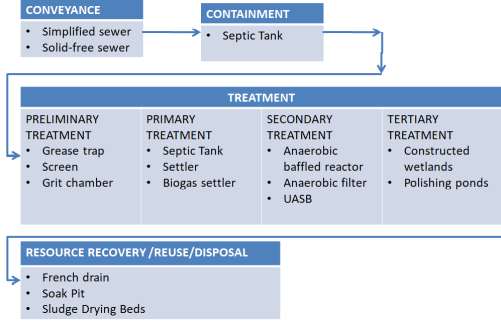
The components of DEWATS are presented in the schematic layout shown in Figure 4.1
Figure 4.27: Treatment Flow Sheet for Components of DEWATS (Source: MoW, 2018)
1.2.1 Containment
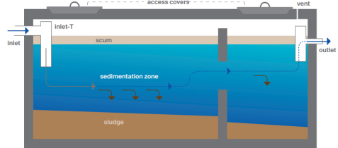
Containment technologies collect and store wastewater at the user interface on-site. Containment technologies are usually applicable for low-cost, non-sewered sanitation (FS) systems as intermediate storage, but can also serve as pre-treatment modules for small-scale wastewater treatment systems. The main containment technology applicable for wastewater treatment technologies is a septic tank (see Figure 4 .28).

Figure 4.28: The Cross Section of a Septic Tank
(Source: MoW, 2018)
In the vast majority of situations, containment systems are already installed on-site but are often improperly designed, constructed and maintained, which poses severe environmental hazards. Apart from septic tanks providing some degree of pre-treatment, the effluent usually contains high concentrations of pollutants, which can carry severe public health and environmental burdens, especially in densely populated urban areas and in the vicinity of drinking water sources. Hence, proper sealing of containment options is crucial for environmental sanitation. Containment systems can also be implemented to buffer peak flows.
1.2.2 Design of Septic Tank
The capacity of septic tank depends on number of users and interval of sludge removal. Normally sludge should be removed every 2 years. The liquid capacity of the tank is taken as 130 litres to 70 litres per head. For small number of users 130 litres per head is sufficient.
A septic tank is usually provided with brick walls in which cement mortar [not less than 20 cm (9 inch)] thick and the foundation floor is of cement concrete 1:2:4. Both inside and outside faces of the wall and top of the floor are plastered with minimum thickness of 12mm thick cement mortar 1:3 mix.
All inside corners of the septic tank are rounded. Water proofing agent (such as Impermo, Cem-seal or Accoproof, etc.) is added to the mortar at the rate of 2% of the cement weight. Water proofing agent is to be added in similar proportion in to the concrete also for making the floor of the tank.
For proper convenience in collection and removal of the sludge, the floor of the septic tank is given a slope of 1:10 to 1:20 towards the inlet side. Which means that the floor of the outlet side will be on the higher elevation than the floor at the inlet side.
1.2.2.1 Dimensioning a Septic Tank
(A) Length, Width and Depth of Septic Tank
Width = 750 mm (minimum)
Length = 2 to 4 times width
Depth = 1,000 to 1,300 mm. (min below water level) + 300 to 450 mm free board
Maximum depth = 1,800 mm + 450 mm free board
Capacity = 1 cubic metre (minimum)
(B) Detention period
Detention period of 24hrs (is mostly) considered in septic tank design. The rate of flow of effluent must be equal to the rate of flow of the influent.
(C) Inlet and outlet pipes
An elbow or T pipe of 100mm diameter is submerged to a depth of 250-600 mm below the liquid level. For the outlet pipe an elbow or T type of 100mm diameter pipe is submerged to a depth of 200-500 mm below the liquid level. Pipes may be of stone ware or asbestos or PVC.
(D) Baffle Walls of the Septic Tank
For small tanks, RCC hanging type scum baffle walls are provided in septic tanks. Baffle walls are provided near the inlet. It is optional near the outlet. The inlet baffle wall is placed at a distance of L/5 from the wall, where L is the length of the wall. The baffle wall is generally extended 150 mm above to scum level and 400-700 mm below it.
Scum being light, generally floats at the water level in the tank. Thickness of the wall varies from 50 mm to 100 mm. For large tanks the lower portion has holes for flow of sludge.
(E) Roofing Slab of the Septic Tank
The top of the septic tank is covered with a RCC slab of thickness of 75-100 mm depending upon the size of the tank. Circular manholes of 500mm clear diameter are provided for inspection and desludging. In case of rectangular opening clear size is kept as 600 x 450 mm.
(F) Ventilation Pipe
For outlet of foul gases and ventilation purpose cast iron or asbestos pipe of 50-100 mm diameter is provided which should extend 2m (minimum) above ground level. Top of the ventilation pipe is provided with a mosquito proof wire mesh or cowl.
1.2.3 Conveyance
Technologies presented in this section are sewer-based technologies, using water from waterborne toilets as a conveying medium.
1.2.3.1 Simplified Sewer
A simplified sewer describes a sewerage network that is constructed using smaller diameter pipes laid at a shallower depth and at a flatter gradient than conventional sewers (Figure 4.3).
