Difference between revisions of "Chapter Seven: Water Treatment"
| Line 127: | Line 127: | ||
show the layout plan and two sections of such a sand trap for small streams | show the layout plan and two sections of such a sand trap for small streams | ||
intake. | intake. | ||
| + | |||
| + | [[Image:Figure7.15.JPG|704px|link=Chapter_Seven:_Water_Treatment]] | ||
| + | |||
| + | [[Image:Figure_7.16.JPG|706px|link=Chapter_Seven:_Water_Treatment]] | ||
| + | |||
| + | [[Image:Figure7.17.JPG|706px|link=Chapter_Seven:_Water_Treatment]] | ||
==== Pre-chlorination ==== | ==== Pre-chlorination ==== | ||
Revision as of 12:22, 2 June 2021
Contents
- 1 Chapter 7: WATER TREATMENT
- 1.1 INTRODUCTION
- 1.2 RECOMMENDED OVERALL DESIGN APPROACH FOR COMPONENTS OF WATER TREATMENT PLANTS
- 1.3 DOCUMENTS AND WEBSITES CONSULTED AND WHICH ARE HYPER-LINKED TO THE DCOM MANUAL
- 1.4 WATER TREATMENT DESIGN CONSIDERATIONS
- 1.5 WATER TREATMENT LEVELS AND UNITS
- 1.5.1 Pre-treatment
- 1.5.1.1 Scum and Floating Materials Skimmer
- 1.5.1.2 Screening or Straining
- 1.5.1.3 Grit Removal
- 1.5.1.4 Design approach
- 1.5.1.5 7.5.1.3.1 Design criteria
- 1.5.1.6 Sand Traps
- 1.5.1.7 Pre-chlorination
- 1.5.1.8 Water pre-conditioning (pH adjustment)
- 1.5.1.9 Primary Treatment
- 1.5.1.10 Sedimentation
- 1.5.1.11 Lamella Plate Settlers (Inclined plate settlers)
- 1.5.1.12 Primary Filtration
- 1.5.1.13 Slow Sand Filtration
- 1.5.1.14 Other Types of Filters
- 1.5.1.14.1 (a)Pressure Filters
- 1.5.1.14.2 (b)Upward Flow Filters
- 1.5.1.14.3 (c)Roughing Filters
- 1.5.1.14.4 (i)Advantages of Roughing filters
- 1.5.1.14.5 (ii)Parameters for Design of Roughing Filter
- 1.5.1.14.6 (iii)Filter Media Size
- 1.5.1.14.7 (iv)Filtration Rates
- 1.5.1.14.8 (v)Filter Media Length
- 1.5.1.14.9 (vi)Filter Media Materials
- 1.5.1.14.10 (vii)Types of Roughing Filters
- 1.5.1.15 (d)Bank Filtration (BF)
- 1.5.1.16 Floatation
- 1.5.1.17 Dissolved-Air Floatation
- 1.5.1.18 Electrolytic Floatation
- 1.5.1.19 Dispersed-Air Floatation
- 1.5.1.20 Aeration
- 1.5.1.21 Spray Aerators
- 1.5.1.21.1 (a)Design details of Spray Aerators
- 1.5.1.21.2 (b)Multiple Tray Aerators
- 1.5.1.21.3 (c)Design details of Multiple Tray Aerators
- 1.5.1.21.4 (d)Cascade Aerators (Gravity Aerator)
- 1.5.1.21.5 (e)Features of Cascade Aerator
- 1.5.1.21.6 (f)Design details of Cascade Aerators
- 1.5.1.21.7 (g)Injection Aerators
- 1.5.1.21.8 (h)Bubble Aerators
- 1.5.2 Secondary Treatment
- 1.5.1 Pre-treatment
1 Chapter 7: WATER TREATMENT
1.1 INTRODUCTION
In this chapter, different categories of the unit operations that are utilized to achieve different water treatment levels are described. It is followed by description of the recommended approach of design of treatment plant components. Emphasis should be given to potential water sources that have undergone investigations on the variability of both the quality and quantity for at least two years. The data gathered should be used for selection of appropriate treatment flow sheets and designing it.
1.1.1 Classification of the qualities of water sources found in Tanzania according to the complexity of its treatment
Water treatment refers to any process that improves the quality of water to make it more acceptable for human consumption. The production of drinking water involves the removal of contaminants from raw water to produce water that is pure enough for human consumption without any short-term or long-term risk of any adverse health effects.
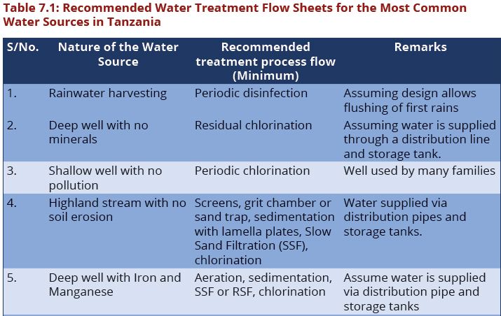
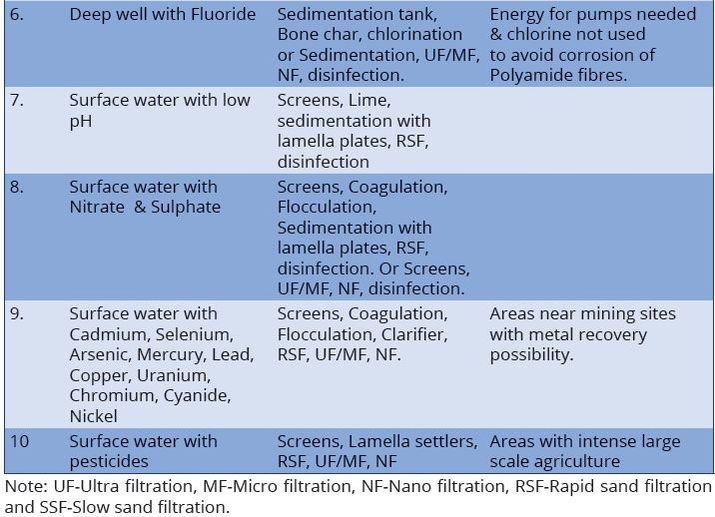
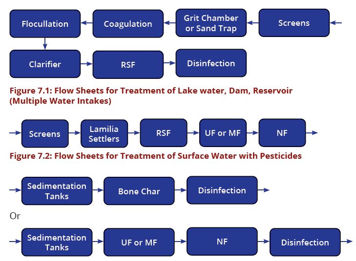
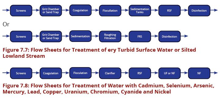
The processes involved in removing contaminants from water includes physical processes such as settling and filtration, chemical processes such as disinfection and coagulation and biological processes such as slow sand filtration. Table7.1 present the recommended treatment process flow for the most common water sources in Tanzania. The above water contaminants removal processes are best presented in water treatment flow sheets (Figures 7.1–7.8).
1.1.2 Classification of Unit Operations to Achieve Water Treatment Levels
Categories for water treatment levels are; pre-treatment, primary treatment, secondary treatment and tertiary treatment.
- Pre-treatment includes units like Scum and floating matters removal, Screening (fine and coarse), Sand trap, Grit removal, Pre-chlorination, Water conditioning (pH correction).
- Primary treatment comprises of Sedimentation, Primary filtration, Floatation, Aeration.
- Secondary treatment includes Coagulation, Flocculation, Clarification, Filtration, Softening, Reverse Osmosis, Capacitive De-Ionisation (CDI), Ion Exchanger, Adsorption, Constructed wetlands.
- Tertiary treatment includes Disinfection, Softening, Water conditioning, Water polishing.
1.2 RECOMMENDED OVERALL DESIGN APPROACH FOR COMPONENTS OF WATER TREATMENT PLANTS
The design of the main conveyance units for the treatment plants including pipes and channels should be designed for a period of 20 years (design life). On other hand, the individual unit operations should be designed for a design period of 10 years in an approach that allows for phased implementation. Intentionally, to allow for adoption of the latest technologies and to avoid tying substantial capital in the treatment plants. It is recommended that a potential water source should be closely and intensely monitored for a period ranging from 2 to 3 years. This period can include the time when the feasibility study for the water supply project is being undertaken including the environmental impact assessments. Water source quality and quantity data should be used for determination of the most suitable treatment flow sheet.
1.3 DOCUMENTS AND WEBSITES CONSULTED AND WHICH ARE HYPER-LINKED TO THE DCOM MANUAL
The following documents were consulted for purposes of making reference for the design of the treatment plants in Tanzania:
- URT, 2009. Design Manual for Water Supply and Wastewater Disposal.
- Ministry of Drinking Water and Sanitation, May 2013. Operation and maintenance manual for rural water supplies. India.
- The Republic of Uganda, Ministry of Water and Environment, 2013. Water Supply Design Manual, 2nd edition.
- World Bank Philippines, February 2012. Water Partnership Program. Rural Water Supply Vol.I Design Manual.
- Washington State Dept. of Health USA, October 2019. Water System Design Manual.
- URT, July 1997. Design Manual for Water Supply and Wastewater Disposal.
Throughout this manual, on a number of occasions the designers are referred to the websites of the Ministry of Water (https://www.maji.go.tz) or RUWASA (https://www.ruwasa.go.tz) vide the various hyperlinks inserted in order to access the standard drawings for various appurtenances.
1.4 WATER TREATMENT DESIGN CONSIDERATIONS
The manual has made reference to a number of design guidelines that are relevant for the design of various unit operations and wherever necessary the full guidelines have been hyper-linked to the manual. For each unit operation, a few critical design criteria have been provided.
Before proposing or designing any treatment plant for any planned water supply project, water quality of the anticipated water sources to be treated has to be known to the designer. Knowing the historical and current water quality trends of the sources will help in designing a treatment plant that can address the localized water quality challenges of concern in the given area apart from the general water quality parameters.
The sizing and selection of the treatment technology and different units to be installed should always aim at meeting the established national and international water quality standards and associated health criteria which are often updated from time to time. There are different criteria and standards across the world, however, in Tanzania, the most recent standards of Tanzania Bureau of Standards and the World Health Organization (WHO) guidelines are the guiding documents recommended to be referred when designing a water supply project.
1.5 WATER TREATMENT LEVELS AND UNITS
1.5.1 Pre-treatment
1.5.1.1 Scum and Floating Materials Skimmer
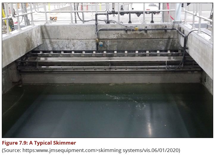
This is the unit operation that enables the manual or automated removal of scum and floating matter ahead of the screening units. These are designed to skim the entire width of the approach area ahead of the screens. In view of the variability of flow of water from the sources, skimmers ought to be designed such that they can be adjusted up or down depending on the quantity variation that is established during the feasibility study. The width of the channel or any open conduit delivering the raw water will determine its design. Figure 7.9 shows the design of such a skimmer.
1.5.1.2 Screening or Straining
This unit operation consists of fine screens and coarse screens which perform the task of removing all fine and coarse matters that may block the screen or damage downstream appurtenances or machines. This is a physical, pretreatment process used to remove weeds, grass, twigs, bilharzial snails and other freshwater crustaceans as well as coarser particles including plastics, tins and other hard matter so that they do not enter the pumping, treatment, or supply system. Screens are placed at the entrance to the intake of a water supply project.
The design considerations for surface water screens are;
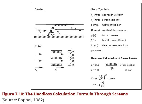
- They should be easily accessible, at least during medium and low flows and inclined downstream of the river or stream as well as during cleaning (if manually done) as indicated in Fig.7.10.
- Distance between bars should be between 10 and 30 cm. for coarse screens and between 0.5 and 5 cm. for fine screens. The shape of the screen bars is either round or rectangular.
- Approach velocity entering the screen (Va) from upstream should not exceed 0.3 to 0.5 m/sec. to limit sedimentation.
- Velocity through the screens (Vs) should not exceed 0.7 to 1.0 m/sec. to prevent soft deformable materials from being forced through the screens.
- The ratio of the width of the screens (Ø) and the space between the bars (b) determines the ratio between the two velocities (Va) and (Vs).
- Small screens are made removable for cleaning, medium-sized can be hand raked in-situ whilst large screens will need in-situ mechanical or electrical operated rakes.
Figure 7.10 presents the formula for the calculation of the headloss through the screens as well as the screen bars coefficient (ƥ).
1.5.1.3 Grit Removal
Grit consists of the heavy inorganic fraction of sewage solids that includes road grit, sand, egg shells, broken glass, coconut shells and metal pieces. The purposes of including grit channels in the design are as follows:
- To protect pumps and other mechanical parts from excessive wear and tear,
- To avoid undue clogging/filling up of subsequent unit operations,
- To differentially remove grit but not the organic particulates in water.
The average specific gravity of grit is 2.5 with an average settling velocity S = 30 mm/sec. In comparison, while sand grit has an average solids density ƥs = 2650 kg/m3organics have a density ƥo ranging from 1020 to 1200 kg/m3.
1.5.1.4 Design approach
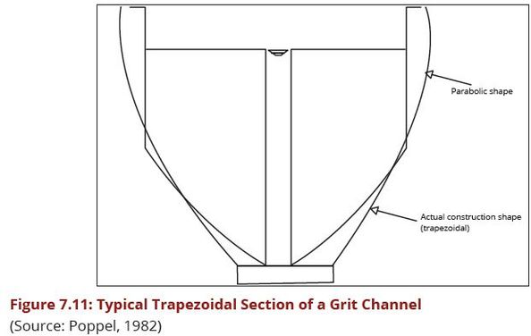
To exploit the differential sedimentation rates of the particles by providing channels that ensure removal of grit rather than any other lighter particles and to maintain the horizontal flow velocity Vh has to be maintained at about 0.3 m/sec. Provision of a parabolic or near parabolic cross section of the channel guarantees that the constant velocity is maintained at all flows. In practise, due to the difficulty of construction of parabolic sections, trapezoidal sections are used.
1.5.1.5 7.5.1.3.1 Design criteria
Length of the channel L = 20 (maximum depth of flow)
L/d = Vh/Vs Where, Vh = Horizontal flow velocity Vs = Vertical settling velocity L = Length of the grit channel D = Depth of flow in the channel
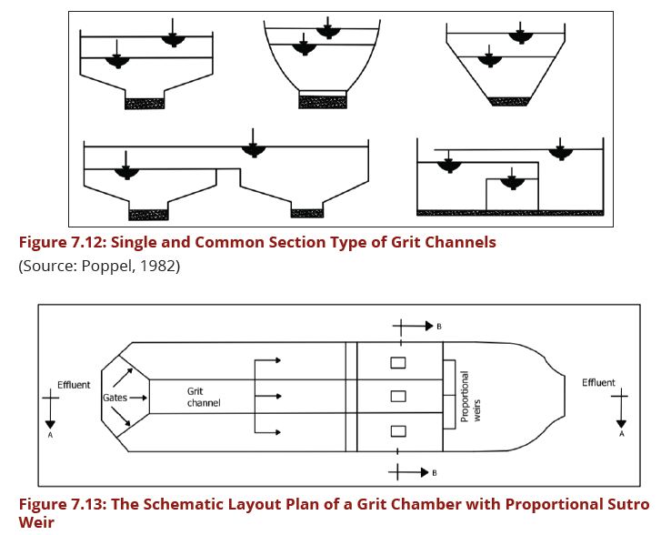
There are three types of grit channels that can be designed, these include horizontal flow, Rotational flow, and Vertical flow
1.5.1.6 Sand Traps
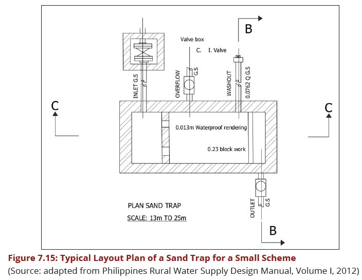
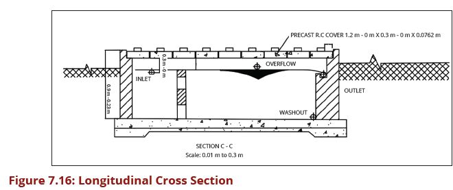
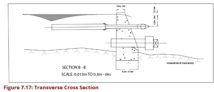
This pre-treatment unit is designed to trap sand after water has been guided into the intake chamber in order to reduce wear and tear as well as silting up the unit operations that are located downstream of the intake structure. The minimum diameter of washout pipes of such sand traps is 75 mm and the bigger the main intake pipe, the bigger is the flushing pipe for sand. Figures 7.15, 7.16 and 7.17 show the layout plan and two sections of such a sand trap for small streams intake.
1.5.1.7 Pre-chlorination
This is a unit operation that is used for purposes of controlling algae growth in raw water and the process of preparation of the chemical to facilitate dosing will include the standard preparation of the aqueous solution as done during disinfection. This is often added upon establishment of occurrence of algal blooms during certain periods of the year as confirmed by laboratory tests undertaken daily. The amount of the dose will be established daily in order to pre-determine the pre-chlorination dose that has to ensure no interference with downstream unit operations in case the flow sheet involves biological treatment processes like slow sand filter or others. The location of dosing of the chemical has to be secured against direct sunlight and has to ensure intense mixing. Where chlorine gas is used for pre-chlorination, the usual measures that are taken when dosing chlorine in gaseous form have to be taken including leakage detection. To minimise chlorine consumption, pre-chlorination has to be done downstream of the fine screens.
Other design features can be seen in the Appendix H. of this DCOM Manual. It should be noted that pre-chlorination also controls growth of bacteria in pipes and tanks (BRITANICA, 2020). Lanfair et al (2020) cautions that if pre-chlorination is applied to water with a high concentration of natural organic matter (nom), the latter is suspected to react with chorine to form Disinfection by-products (DBPs) that include trihalomethanes or haloacetic acids that are suspected to contribute towards stomach and bladder cancer.
1.5.1.8 Water pre-conditioning (pH adjustment)
Water pre-conditioning can entail a number of pre-treatments undertaken prior to pre- chlorination which is often the final step in pre-treatment. This unit operation involves adjustment of the pH upstream in order to ensure the chemicals used during further treatment processes are dosed to water that has the correct pH range for maximum efficiency. A good example is when the treatment flow sheet includes coagulation with Ferrous Sulphate that requires an optimum pH range of 7 to 8.5. As a matter of fact,the application of this unit operation guarantees that the daily fluctuations in quality are also reflected in the chemical that is used for pH correction whether an acid or an alkali is used. It is usual to apply lime for increasing pH and use of acids like dilute sulphuric acid or hydrochloric acid. Other pre-conditioning measures include use of sodium carbonate (soda ash) to remove hardness (i.e. calcium carbonate).
1.5.1.9 Primary Treatment
Primary treatment of water removes material that will either float or readily settle out by gravity. This water treatment level includes the physical processes of screening, grit removal and sedimentation.
1.5.1.10 Sedimentation
In designing sedimentation tanks, the required detention time determines the dimensions of the tank. A rectangular tank is the simplest design to use. Detention time is calculated as Volume/Flow rate (Q). The detention times based on the average daily flows and usually range from about 45 minutes to 3 hours depending on water turbidity. The ideal inlet reduces the entrance velocity and distributes the water as uniformly as possible across the depth and width of the tank. Outlets are usually weirs which are sufficiently long to reduce the flow velocity, and so avoid the re-suspension of the solids in the water. Plain sedimentation tanks should be designed for a surface loading in the range of 0.1 - 0.5 m3/m2/h. The exact surface loading to be adopted should be determined after carrying out settlement tests on samples of raw water, typical of all regimes of the water source. The settling properties of water will depend on the soil and vegetation conditions in the catchment area, and they will vary considerably between different locations and regimes of the water source. Figure 7.18 (a and b) shows a cross section through a circular sedimentation tank while figure Figure 7.19 (a) and (b) shows a cross section through a rectangular sedimentation tank.
- Example.jpg
Caption1
- Example.jpg
Caption2
- Example.jpg
Caption1
- Example.jpg
Caption2
</gallery> </gallery>
1.5.1.11 Lamella Plate Settlers (Inclined plate settlers)
Settling efficiency of a basin depends upon the design surface loading. Lamella plates and small diameter tubes having a large wetted perimeter, relative to wetted area providing laminar flow conditions and low surface loading rates have shown good results in terms of settling efficiency and economy in space as well as cost. Plate or tube configuration can be horizontal or steeply inclined. In inclined plates or tubes (55o – 60o) continuous gravity drainage of the settleable material onto the floor below can be achieved, without impairment of effluent quality. However, to work effectively an efficient flocculation stage is critical.
In purpose built lamella plate settlers the water enters at the base of the lamella plates and travels upwards between the lamellas. Each space between the lamella plates tends to act as a semi -independent settling modules with the lamella plates extending from near the base of the tank to about 125 mm above the top water level. The clarified water is collected by saw-toothed notched launders running along each side of the plate. Unless sludge is removed mechanically by a scraper, sufficient depth beneath the plates is required for access during cleaning, although this can be aided by pressurised water. A typical arrangement is illustrated in Figure 7.20.
- Example.jpg
Caption1
- Example.jpg
Caption2
</gallery>
Plates are made of stainless steel or plastics with a width of 1.25 to 1.5 m and a length of 2.5 to 3.25 m including the length above water. It is advisable to use standard lengths of metal sheets and plastic sheets available in the market. In Tanzania sheets are in dimensions of 120 cm x 240 cm. Plate thickness is usually about 0.7 mm for stainless steel whilst the horizontal spacing between plates is varied according to the nature of the raw water but within the range 50 – 80 mm.
Total settled area is then:
A = (n-1) × L × W × cos θ (7.2)
Where; n = number of plates L = plate length in water (m), less the transition length W = the plate width (mm), and θ = the angle of inclination of the plates to the horizontal (55o – 60o) A = Settled area (m2)
Table 7.2: Important parameters for the design of lamella plate settler.
| S/No | Parameter | Units | Range |
|---|---|---|---|
| 1 | Surface8 loading rate | m/h | 5 to 10 m/h9 |
| 2 | Hydraulic Loading Ratio | - | 0.25 -0.5 |
| 3 | Angle of inclination of the plates, θ | - | 45-70o Typical: 60o |
| 4 | Plate spacing, w | mm | Min 20 |
- Example.jpg
Caption1
- Example.jpg
Caption2
1.5.1.12 Primary Filtration
Primary filtration of water removes material through filtration whose particles size is greater than the opening size. The target particles are the ones which are not removed by sedimentation tanks.
1.5.1.13 Slow Sand Filtration
A Slow Sand Filter (SSF) is basically a large tank containing the sand bed. A distinguishing feature of slow sand filters is the presence of a thin layer, called the schmutzdecke, which forms on the surface of the sand bed and includes a large variety of biologically active micro-organisms.
Water is introduced at the top and trickles down through the sand bed to the under- drains and goes to the storage tank. The impurities in the water are retained at the upper layers of the sand bed. In the process, the schmutzdecke consisting of bacteria and microscopic plants grow. The schmutzdecke removes the organic matter and most of the pathogenic micro-organisms in water which might be smaller than the pores of the sand.
- Example.jpg
Caption1
- Example.jpg
Caption2
1.5.1.13.1 (a)Elements of a Slow Sand filter
Figure 3.43(a) presents, in diagrammatic form the various elements that go to make up a Slow Sand Filter. Essentially the SSF elements consist of:
(i)a supernatant (raw) water reservoir, the principal function of which is to maintain a constant head of water above the filter medium, this head providing the pressure that carries the water through the filter;
(ii)a bed of filter medium (nearly always sand), with in and upon which the various purification processes take place
(iii)an under-drainage system, which fills the dual purpose of supporting the filter medium while presenting the minimum possible obstruction to the treated water as if emerges from the underside of the filter-bed; and
(iv)a system of control valves to regulate the velocity of flow through the bed, to prevent the level in the raw water reservoir from dropping below a predetermined minimum during operation, and to permit water levels to be adjusted and backfilling to take place when the filter is put back into operation after cleaning
(v)It comprises approximately 1.2 m depth of fine sand supported on two or three gravel layers. The effective size of the sand used in slow sand filters is about 0.2 mm, but may range between 0.15 mm and 0.35 mm, and with a coefficient of uniformity of between 1.5 and 3.0.
(vi)It is a very simple and effective technique for purifying surface water. It will remove practically all of the turbidity from the water as well as most of the pathogens without the addition of chemicals. Slow sand filters can frequently be constructed largely from locally-available materials.
In a SSF the water is purified by slow percolation through a bed of fine sand. Pre- treatment is necessary with raw waters having an average turbidity of 25 NTU or more, but should be considered also for less turbid raw waters 5 to 25 NTU) to improve effluent quality and reduce frequency of cleaning. The SSF is also useful for treating groundwater containing solids in suspension, e.g. ferric and manganese compounds converted by aeration from the soluble state of the salts.
Table 7.3 below shows the typical performance of the Slow Sand Filter.
| Parameter of Water Quality | Purification Effect of Slow Sand Filtration |
|---|---|
| Colour | 30% to 100% reduction |
| Turbidity | Turbidity is generally reduced to less than 1 NTU |
| Faecal Coliforms | 95% to 100%, and often 99% to 100%, reduction in the level of faecal coliforms |
| Cercariae | Virtual removal of cercariae of schistosomes, cysts
and ova |
| Viruses | Virtually complete removal |
| Organic matter | 60% to 75% reduction in COD |
| Iron and manganese | Largely removed |
| Heavy metals | 30% to 95% reduction |
(Source: 3rd Design manual for water supply and waste water disposal, 2009)
1.5.1.13.2 (b)Design Considerations of Slow Sand Filter (SSF)
- Raw water quality and necessity for pre—treatment and/or aeration;
- Necessity for chlorination room and clear water storage, pumping and distribution;
- Site location, foundation conditions, space for expansion and pre-treatment;
- Availability of source of filter media, and construction materials;
- Fencing and security
- The filter sand must be free from any clay or silt content and preferably of a well- rounded quartz material. Organic matter should be avoided.
1.5.1.13.3 (c)Design Criteria;
- When choosing the filter sand, the grain size distribution should meet the effective size 0.15 to 0.35 mm and the coefficient of uniformity should be less than 3 ,
- In order to calculate for the total area of filter beds, a working rate of 0.1 - 0.2, m3/m2/hr is recommended. When one filter is not operational, the working rate of the remaining filter should not exceed 0.2 m3/m2/h.
- The turbidity in the incoming water should not exceed an average of 5 - 10 NTU. In cases of higher turbidity, preliminary treatment such as roughing filters is necessary
- The inlet structure should be designed in such a way that the raw water is equally distributed over the filter bed area.
- To achieve this, the inlet velocity should be around 0.1 m/s and the width of the inlet structure should be at least (0.05 x Q) metres, where Q is the design flow in m3/h.
- The minimum size of a filter unit should be 15 to 20 m2;
- The height of the supernatant water should be 1 to 1.5 m,
- The oxygen content of the water after filtration should not be less than 3 mg/l.
- Calculate filter surface area = flow capacity (m3) / rate of filtration
1.5.1.13.4 (d)Main Water Under-drain
- Calculate Diameter of the under drain = (22 × d2) / (28 × r)
- Area of holes or slots to be 1.5% of area of the filter
- As a check, the oxygen content of the water after filtration should not be less than 3 mg/l.
- Freeboard above water level = 0.2 - 0.3 m
- Height of walls above ground surface= > 0.8 m
- Gravel filter support = 0.3 - 0.5 m
- Depth of under—drainage system = 0.3 - 0.5m
- Area (A) per filter bed = 10 - 100 m2
1.5.1.13.5 Rapid Gravity Sand Filtration
This is a process in which water flows onto the top of the filter media and is driven through it by gravity. In passing through the small spaces between the filter's sand grains, impurities are removed. The water continues its way through the support gravel, enters the under-drain system, and then flows to the reservoir. It is the filter media which actually removes the particles from the water. The filter media is routinely cleaned by means of a backwashing process.
Rapid Sand Filtration (RSF) is a technique commonly used for treating large quantities of drinking water. It is a relatively sophisticated process usually requiring power- operated pumps for backwashing or cleaning the filter bed, and some designs require flow control of the filter outlet. A continuously operating filter will usually require backwashing about every two days or so when raw water is of relatively low turbidity and at least daily during periods of high turbidity. Because of the higher filtration rates, the area requirement for a rapid gravity filtration plant is about 20% of that required for slow sand filters.
Surface loading should be between 4 and 7 m3/h.m2, and the filter structure should be designed with a minimum height between the top of the filter media and the bottom of the wash water channel of at least 30% of the height of the filter media as this expands during backwashing. It may be necessary to include for air-scour as well as backwashing, or for the two combined in a single operation.
Normally a sufficient distribution of the wash water will be achieved if:
- Ratio of area of orifice to area of bed served (1.5 to 5) × (103) : 1
- Ratio of area of main to laterals served (1.5 to 3) : 1
- Diameter of orifices 5 - 20 mm
- Spacing of orifices 100 - 300 mm centre to centre
- Spacing of laterals approximating to the spacing of orifices.
The filter bed should be approximately 1.0 m thick and preferably consist of well- rounded quartz sand with an effect size of 0.7 - 1.0 mm and uniformity coefficient in the range of 1.3 - 1. 5. The available hydraulic head above the top of the filter bed should be 1.3 - 1.5 m. The following stratification of the sub structure should be used to support a filter of an effective grain size as suggested earlier (finest strata at the top).
- 0.15 m of grain size 2 - 2.8 mm
- 0.10 m of grain size 5.6 - 8 mm
- 0.10 m of grain size 10 - 20 mm
- 0.10 m of grain size 20 - 40 mm
- 0.10 m of grain size 40 - 60 mm
The washing velocity should be in the range of 35 – 55 m3/m2/hour, however care must be taken to ensure that sand carry over into the wash-water channel does not occur and the actual wash-water rate adjusted accordingly.
In order to achieve proper washing of the filter a storage volume sufficient for continuous washing for an 8 to 10 minute period should be available.
1.5.1.13.6 (b)Design Steps
The following design steps should be followed;
(i)Filter Units
- Rate of filtration should be 4 - 6 m3/m2/hr
- Determine flow capacity in the filter (m3/day. demand)
- Calculate filter surface area = flow capacity (m3) / rate of filtration
(ii)Main Water Under-drain
- Select flow capacity and flow velocity
- Calculate area required = (low capacity)/ (low velocity) (m2)
- Calculate diameter of the under drain, d= Square Root of (4A/Π)
- Area of holes = 0.2 - 0.4 % of the area of filter
- Use five layers of sand particles in the filter as indicated above:
- Water depth 1 – 1.2 m
- Sand depth 1 – 1.2 m
1.5.1.13.7 (c)Filter Backwashing
A major cause of poor performance by rapid gravity filters is a result of either inadequate or excessive backwashing rates. Backwashing is sometimes carried out by water alone but more often by air and water usually applied one after the other by reverse flow to the filter bed. The first operation however is to allow the filter to drain down until the water lies a few centimetres above the top of the bed. Air is then introduced through the collector system at a rate of about 6.5 to 7.5 mm/s.
Where air and water is applied separately, air scour normally lasts about 3 – 4 minutes and the water wash about 4 – 6 minutes. Where applied concurrently, air is first introduced and after about 1.5 – 2 minutes when it is fully established water is introduced and the combined backwash last for about 6 – 8 minutes. Air is stopped first and the water run for several more minutes to rinse the bed. Generally, total water consumption per wash amounts to about 2.5 bed volumes, but should normally not exceed 2% of the treated water output in well run plants.
Comparison between Slow Sand Filters and Rapid Sand Filters
a)Base material: In SSF it varies from 3 to 65 mm in size and 30 to 75 cm in depth while in RSF it varies from 3 to 40 mm in size and its depth is slightly more, i.e. about 60 to 90 cm.
b)Filter sand: In SSF the effective size ranges between 0.2 to 0.4 mm and uniformity coefficient between 1.8 to 2.5 or 3.0. In RSF the effective size ranges between 0.35 to 0.55 and uniformity coefficient between 1.2 to 1.8.
c)Rate of filtration: In SSF it is small, such as 100 to 200 L/h/sq.m. of filter area while in RSF it is large, such as 3000 to 6000 L/h/sq.m. of filter area.
d)Flexibility: SSF are not flexible for meeting variation in demand whereas RSF are quite flexible for meeting reasonable variations in demand.
e)Post treatment required: Almost pure water is obtained from SSF. However, water may be disinfected slightly to make it completely safe. Disinfection is a must after RSF.
f)Method of cleaning: Scrapping and removing of the top 1.5 to 3 cm thick layer is done to clean SSF. To clean RSF, sand is agitated and backwashed with or without compressed air.
g)Loss of head: In case of SSF approx. 10 cm is the initial loss, and 0.8 to 1.2m is the final limit when cleaning is required. For RSF 0.3m is the initial loss, and 2.5 to 3.5m is the final limit when cleaning is required.
1.5.1.14 Other Types of Filters
1.5.1.14.1 (a)Pressure Filters
Pressure filters are circular pressurised vessels containing the filter media and usually designed for vertical flow. They work on the same principle as rapid gravity filters differing in that the filter medium is enclosed in a steel vessel and the water is forced through it under pressure.
1.5.1.14.2 (b)Upward Flow Filters
Upward flow filters are theoretically more efficient than gravity filters where the water to be filtered flows upwards through the naturally desegregated, progressively finer and finer media so that coarser particles are trapped first in the coarser bottom layers. This tends to extend the period between backwashing. Several sand grades, getting progressively finer upwards have also been used in which case some restraining means such as a grid is required often located about 0.1 m below the surface where upward backwashing is used.
The major reason why RSF is a preferred option of water filtration to SSF is rate of filtration where RSF is higher per filter area flexibility, where SSF are not flexible for meeting variation in demand, method of cleaning where in the case of RSF, no sand is lost. Also RSF requires minimal land requirement (Source: Ugandan Water Supply Design Manual (2013).
1.5.1.14.3 (c)Roughing Filters
Roughing filters have their place as a form of primary treatment, especially for turbid or highly changeable river water. This technique of primary treatment has been greatly under-utilised in Tanzania in the past. Although much research has been undertaken since late 1970s (Mbwette & Wegelin, 1984). It is used primarily to remove solids from high turbidity source waters prior to treatment with such unit operations as slow sand filters.
In a typical roughing filter, there are series of tanks which are filled with progressively smaller diameter media in the direction of the flow which can either be horizontal or vertical. With respect to the vertical flow direction, up-flow or down-flow roughing filters can be designed. The media in the tank which may include gravel, rice husks or any other suitable local material, plays an important role of reducing the vertical settling distance of the particles to a distance of a few millimetres
1.5.1.14.4 (i)Advantages of Roughing filters
- Can considerably reduce the number of pathogens in the water, as well as the amount of iron and manganese.
- Can be considered a major pre-treatment process for turbid surface water since they efficiently separate fine solid particles over prolonged periods.
- Long filters (10 m) at low filtration rates (0.5 m/h) are capable of reducing high suspended solids concentrations (1000 mg/l TSS down to less than 3 mg/l).
- Capable of reducing peak turbidities by 80 to 90 percent and faecal coliforms by 77 to 89 percent.
- They are placed at the treatment plant site and operated in combination with other pre-treatment units such as dynamic filters or sedimentation tanks.
NB: For detailed information, designers are recommended to download the comprehensive SANDTEC design report entitled ‗Surface Water Treatment by Roughing Filters, A Design, Construction and Operation Manual‘ available at http//sandec.ch/WaterTreatment/Documents/Surface%20Water%20Treatment.pdf Features of Roughing Filters (RF).
The main part of the filter is the section containing the filter material. However, a Roughing filter comprises the following six elements:-
- Inlet Flow Control
- Raw Water Distribution
- Actual Filter
- Treated Water Collection
- Outlet Flow Control
- Drainage System
1.5.1.14.5 (ii)Parameters for Design of Roughing Filter
- Filter media size
- Filtration Rates
- Filter Length
- Filter media materials
1.5.1.14.6 (iii)Filter Media Size
- The size of filter media decreases successively in the direction of water flow and ideally the uniformity of filter media fractions is maximized to increase filter pore space (storage capacity) and aid in filter cleaning (Boller, 1993).
- The use of multiple grades of filter media in a roughing filter promotes the penetration of particles throughout the filter bed and takes advantage of the large storage capacities offered by larger media and high removal efficiencies offered by small media
- The effect of surface porosity and roughness of filter media on particle removal efficiency in roughing filtration is insignificant compared to the size and shape of macro-pores in the filter (Wegelin, 1986)
- Media types commonly used in roughing filtration are quartz, sand and gravels but can be replaced by any clean, insoluble and mechanically resistant material (Graham, 1988)
- Common grades of media used in roughing filters are provided in the Table 7.4
Table 7.4: Different sizes of media in a Roughing filter
| Roughing Filter description | 1st compartment | 2nd Compartment | 3rd Compartment |
|---|---|---|---|
| Coarse | 24-16 | 18-12 | 12=8 |
| Normal | 18-12 | 12-8 | 8-4 |
| Fine | 12-8 | 8-4 | 4-2 |
(Source: Onyeka Nkwonta* and George Ochieng (1996))
1.5.1.14.7 (iv)Filtration Rates
- Filtration rate has a significant influence on the treatment removal.
- Good removal in roughing filters are best achieved with low filtration rate (Boller, 1993), because low filtration rates are critical to retain particles that are gravitationally deposited to the surface of the media.
- While used as pretreatments for iron and manganese removal, it can operate at filtration rates of 1.5 - 3 m/h (Hatva, 1988). It is reported that horizontal flow roughing filter is capable of removing metals like iron, manganese, turbidity and color at a filtration rate of 1.8 m/h (Dastanaie, 2007)
- At increased filtration rates (2 m/h), coarse particles penetrate deeper into the bed and they cause decrease in filter efficiency (Wegelin et al. (1986). Whereas at 1 m/h there is good distribution of solids loading throughout the bed. Hendricks (1991) also suggested that normal filtration rate of horizontal roughing filters is between 0.3 and 1.5 m/h.
1.5.1.14.8 (v)Filter Media Length
- Improved cumulative removal efficiencies are typically correlated to longer filter lengths (Collins, 1994; Wegelin, 1986).
- Incremental removal efficiencies decreases with increasing filter length due to the preferential removal of larger particles early in the filter (Wegelin, 1996).
- The rate of decline is dependent on filter design variables and the size and nature of particles in suspension. The use of different media sizes may allow for treatment targets to be met by a shorter filter with multiple media sizes compared to with long filter packed with one media size.
1.5.1.14.9 (vi)Filter Media Materials
The following material could therefore be used as filter media:
a)Gravel from a river bed or from the ground.
b)Broken stones or rocks from a quarry.
c)Broken burnt clay bricks.
d)Plastic material either as chips or modules (e.g. used for trickling filters) may be used if the material is locally available.
e)Burnt charcoal, although there is a risk of disintegration when cleaning the filter material, should only be considered in special cases (e.g. for removal of dissolved organic matter).
f)Coconut fibre, however, due to the risk of flavoring the water during long filter operation, should be used with care.
g)Broken burnt bricks and improved agricultural waste (e.g. charcoal, maize cobs), can also be effectively used as pretreatment media (Ochieng (2006) and therefore could serve as alternatives where natural gravel is not readily available.
1.5.1.14.10 (vii)Types of Roughing Filters
There are many types of roughing filters with different flow directions and with different types of filter medium (e.g. sand, gravel, coconut husk fibre). However the common types are:
i.Horizontal Flow Filters (HRF)
ii.Vertical (VRF)
iii.Dynamic (DRF)
1.5.1.15 (d)Bank Filtration (BF)
Bank filtration (BF) is the infiltration of surface water, mostly from a river system into a groundwater system induced by water abstraction close to the surface water (e.g. river bank). This water abstraction is commonly done by operating wells.
As the water flows through the soil, it is filtered and hence its quality is improved. In the context of developing or newly-industrialised countries, bank filtration may contribute to a more sustainable water cycle by recharging stressed groundwater bodies with filtered surface water. (Sharma & Amy 2009; Huelshoff et al.)
Bank filtration is a water treatment technology that consists of extracting water from rivers by pumping wells located in the adjacent alluvial aquifer. During the underground passage, a series of physical, chemical, and biological processes take place, improving the quality of the surface water, substituting or reducing conventional drinking water treatment.
Bank filtration works by pumping pressure in the alluvial aquifer adjacent to the river that forces the water to percolate from the river into the aquifer. In this path, a series of physical and biogeochemical processes take place, including physical filtration, adsorption, absorption, biodegradation, and dilution. Thus, riverbank-filtrate often shows better quality than river water, making its treatment for human consumption easier and less expensive.
The removal of sediment, organic and inorganic compounds, and pathogens takes place during the first metres from the river in what is known as the hyporheic zone, which usually presents reducing conditions due to the high microbial activity which consumes the oxygen in the water. Within this zone there are important biochemical processes and Redox reactions that affect groundwater quality.
The efficiency of BF depends on the local conditions including the hydrology and hydrogeology of the site, the geochemistry of water (from both the river and the aquifer), the geochemistry of microbial populations, and associated metabolic activity. This is the reason as to why it is difficult to define general procedures for identifying appropriate sites to implement the BF technique, as well as the expected efficiency of the process.
One limitation on the efficiency of BF is the clogging of the bed and the banks of the river, which decreases the hydraulic conductivity in the hyporheic zone. This clogging can be caused by infiltration of the fine sediments, gas entrapment, bio-film formation related to microbiological activity, or the precipitation and co-precipitation of inorganic compounds, being the first of these the most influential factor in clogging formation.
Siting and Design Parameters
- The most important parameters for success during BF are the flow path length, the thickness of the aquifer, and the infiltration area in the river (Grischek et al. (2002).
- The siting and design of a BF system depend on hydrogeological, technical, economical, regulatory, and land-use factors.
- Riverbank filtration wells can be designed either vertically (as the most common practice especially for the extraction of low water quantities) or horizontally (for higher extraction rates).
- Local factors such as river hydrology, hydrogeological site conditions (i.e., aquifer thickness and hydraulic conductivity), and the aims of water withdrawal are used to determine the capacity of the wells, the travel time of the bank filtrate, distance between the river and the well.
- Horizontal wells (sometimes with a radial pattern), also known as collector wells, are directed toward the river and extract water from beneath the riverbed, whereas vertical wells extract water along the riverbed.
- The BF wells can also be distributed parallel to the riverbank in galleries or groups
1.5.1.16 Floatation
Floatation may be defined as the transfer of a suspended phase from the bulk of a dispersion medium to the atmosphere/liquid interface by means of bubble attachment. There are three basic processes involved which are: bubble generation, bubble attachment and solids separation.
Floatation is described as a gravity separation process, in which gas bubbles attach to solid particles to cause the apparent density of the bubble-solid agglomerates to be less than that of the water thereby allowing the agglomerates to float to the surface. The different methods of producing the gas bubbles give rise to different types of Floatation processes which are Dissolved-air Floatation, Electrolytic Floatation and Dispersed-air Floatation.
1.5.1.17 Dissolved-Air Floatation
This is a relatively new solution for the clarification of surface and ground waters. The process as shown in Fig 7.24 is relatively simple and can be very effective. After flocculation, the produced floc attaches to micro-bubbles and rises to the water's surface. The floated solids are periodically evacuated either hydraulically or mechanically, depending on the sludge concentration required.
- Example.jpg
Caption1
- Example.jpg
Caption2
</gallery>
The dissolved air flotation process can be a good solution for the treatment of water with a high concentration of algae or other low density particles. The system is said to have a number of advantages including:
a.Reliable removal of algae, cryptosporidium and giardia cysts b.Removal of colour and taste compounds c.Removal of low-density solids d.No polymer required e.Concentrated sludge f.Rapid start-up after shutdown g.Few mechanical components h.Low operating costs
The removal of suspended matter solids is achieved by dissolving air in the water under pressure and then releasing the air at atmospheric pressure in a floatation tank basin. The released air forms tiny bubbles which adhere to the suspended matter causing the suspended matter to float to the surface of the water where it may then be removed by a skimming device. Drinking water supplies that are particularly vulnerable to unicellular algal blooms, and supplies with low turbidity and high colour often employ DAF.
1.5.1.18 Electrolytic Floatation
The basis of electrolytic or electro-Floatation is the generation of bubbles of hydrogen and oxygen in a dilute aqueous solution by passing a direct current between two electrodes. Electrical power is supplied to the electrodes at a low voltage potential of 5 to 10 VDC by means of a transformer rectifier. The energy required for electro- Floatation depends largely on the conductivity of the liquid and the distance between the electrodes.
1.5.1.19 Dispersed-Air Floatation
Both foam and froth dispersed air Floatation are unsuitable for water treatment applications because the bubble size tends to be large (>1 mm. compared to 20-111 for dissolved-air Floatation and electro-Floatation) and either high turbulence (froth Floatation) which would break up the fragile flocs formed during the chemical pre- treatment, or undesirable chemicals (foam Floatation) are required to produce the air bubbles required for Floatation. Appendix B.4 (iii) illustrate the Performance of the Dispersed-Air Floatation
1.5.1.20 Aeration
Aeration is the process whereby water is brought into intimate contact with air. Aeration has a large number of uses in water treatment for the following purposes:
i.Increasing dissolved oxygen content in the water; ii.Reducing tastes and odours caused by dissolved gases in the water, such as hydrogen sulphide, which are then released; and also to oxidise and remove organic matter; iii.Decreasing carbon dioxide content of water and thereby reduce its corrosiveness and raise its pH value; iv.Oxidizing iron and manganese from their soluble states to their insoluble states and thereby cause them to precipitate so that they may be removed by clarification and filtration processes; v.Reduction of radon; and vi.Removing certain volatile organic compounds.
Aeration is widely used for the treatment of groundwater having unacceptably high contents of dissolved iron and/ or manganese. The atmospheric oxygen brought into the water through aeration, reacts with the dissolved ferrous and manganous compounds, changing them into insoluble ferric and manganic oxide hydrates. The hydrates can then be removed by the subsequent processes of sedimentation and/or filtration.
Chemicals removed or oxidized by Aeration a)Ammonia b)Chlorine c)Carbon dioxide d)Hydrogen sulphide e)Methane f)Iron and Manganese g)Volatile organic chemicals, such as benzene (found in gasoline), or trichloroethylene, dichloroethylene, and perchloroethylene (used in dry- cleaning or industrial processes)
Types of Aerators Aerators fall into two categories:
- Falling water aerators
- Injection aerators
Falling Water Aerators In the falling water aerators, water is dropped through air and in the second group air is introduced in to the water as small bubbles. Falling water aerators can be divided into: (i)Spray Aerators (ii)Multiple Tray Aerators (iii)Cascade Aerators
1.5.1.21 Spray Aerators
Water is sprayed through nozzles upward into the atmosphere and broken up into either a mist or droplets. Water is directed vertically or at a slight inclination to the vertical. The installation consists of trays and fixed nozzles on a pipe grid with necessary outlet arrangement.
1.5.1.21.1 (a)Design details of Spray Aerators
- Nozzles usually have diameters varying from 10 to 40 mm, spaced along the pipe at intervals of 0.5 to 1m or more. Special (patented) types of corrosion resistant nozzles and sometimes plain openings in pipes, serving as orifices are used.
- The pressure required at the nozzle head is usually 7 m of water but in practice, varies from 2 – 9 m and the discharge rating per nozzle varies form 30 - 600 l/min
- Aerator areas are usually 30 – 90 m2 per 1,000 m3/hr.
- The ‗Dresden‘ type of nozzles gives very good results in removing CO2 and in adding O2 but is poor for radon removal.
1.5.1.21.2 (b)Multiple Tray Aerators
These aerators consist of a series of trays with perforated bottoms. The trays are filled with coke, stone or ceramic balls, limestone, or other materials having a catalytic effect on iron removal. The primary purpose of the materials is providing additional surface contact area between the air and water. Through perforated pipes, the water is divided evenly over the upper tray, from which it trickles down, the droplets being dispersed and re-collected at each successive tray. Appendix B.5 (iii) illustrate the Multiple Tray Aerators.
1.5.1.21.3 (c)Design details of Multiple Tray Aerators
- 3-5 trays are normally used at the intervals of 0.3 - 0.7 m which means that the head needed is 1.5 – 3 m.
- The area required is 40 m2 per 1,000 m3/hr. These aerators have good CO2 removal and good 02 increases (3rd edition Design Manual, 2009).
- The design surface loading of a multiple tray aerator should be of the order of 70 m3/hour/m2 (Water supply Design Manual, Uganda (2013).
However, disadvantages of Multiple Tray Aerators are:
- risk of clogging
- difficult cleaning and breeding places for worms
1.5.1.21.4 (d)Cascade Aerators (Gravity Aerator)
The Cascade Aerators are the simplest type of free-fall aerators and will take large quantities of water in a comparatively small area and at low head. They are simple to keep clean and can be made of robust durable material such as reinforced concrete and are best in the open air. Turbulence is secured by allowing the water to pass through a series of steps or baffles (3rd edition Design Manual, 2009).
1.5.1.21.5 (e)Features of Cascade Aerator
a)A cascade aerator consists of a flight of 4 - 6 steps, each about 300 mm high, to produce turbulence and thus enhance the aeration efficiency, obstacles are often sat at the edge of each step as illustrated in Figure 7.25. b)The design capacity of a cascade aerator should be of the order of 3 35 m /hour per meter of width. c)Exposure time can be increased by increasing the number of steps which is normally between 3 - 10. d)The fall in each step is usually between 0.15 - 0.6 m. The area required is about 40 m2 per 1,000 m3/hr. e)The efficiency for raising 02 content is good and can reach 2.5 kg O2/kWh, but that for CO2 removal rarely better than 60 – 70 %, whilst radon reduction can exceed 50%. f)The principle is to spread the water as much as possible and let it flow over obstructions to produce turbulence. g)These are similar to tray aerators, but with a series of steps or platforms over which the water cascades. Obstacles may be placed on the edge of each step. h)Cascades aerators generally take up more space than tray aerators, but the overall head loss is lower, and maintenance is minimal. i)Where space permits, Cascade aerators are the preferred type of aerator.
- Example.jpg
Caption1
- Example.jpg
Caption2
</gallery>
1.5.1.21.6 (f)Design details of Cascade Aerators
- Number of drops = 4-6
- Height of drops = 30-60 cm
- Overflow rate = 0.01 m3/s over meter width of step
- Height of aerator = 2-3 m
- Cascade area = 1.5-2.0 m2/m3/min of flow
1.5.1.21.7 (g)Injection Aerators
These aerators have a good efficiency in raising O2 content but poor CO2 removal. They can be categorised as: a)Bubble Aerators b)Venturi Aerators c)Brush Aerators d)Inka Aerators
1.5.1.21.8 (h)Bubble Aerators
In these aerators, air is blown to the bottom of the tank through porous filters. Bubble aerators are often applied to existing treatment plants where no spare hydraulic head is available
(a)Design details of Bubble Aerators i.The depth of the tank is 3 - 4.5 m and the width about 2 times the depth. ii.Detention time in the tank is 10 - 20 minutes. iii.Air required is 40 – 120 m2 per 1,000 m3/hr, being 40% to 80% of water capacity. iv.The air bubbles should be as small as possible but the clogging of the filters interfere with that aspect. v.Good mixing in an aeration tank improves efficiency..
(b)Venturi Aerators In venturi aerators air is not blown into the water but is drawn in by a venturi. The 02 improvements is good but CO2 removal is poor.
(c)Brush Aerator This type of aerator consists of a revolving drum, diameter about 0.5 m, submerged about 0.4m of the diameter, and rotating about 100 rpm. However, this type is not commonly used for water treatment.
(d)Inka Aerators This aerator consists of a perforated stainless steel plate under which air is blown. Water flows over the plate. The air water ratio is very high. It can be as high as 100:1. This amount of air causes heavy turbulence and so O2 raising efficiency and CO2 removal are good. Energy consumption is rather high corresponding to a hydraulic head of 7m if air water ratio is 100. A disadvantage is the clogging of the perforated plate.
1.5.2 Secondary Treatment
In this DCOM Manual, the following unit operations have been described in detail as secondary treatment. However, constructed wetlands are simply mentioned because they are described in detail in volume II of the manual.
- Coagulation
- Flocculation
- Clarification
- Filtration (SSF, RSF and other types)
- Reverse Osmosis
- Membrane Filtration (ultrafiltration (UF), Microfiltration (MF), nanofiltration (NF)
- Ion Exchange
- Adsorption
- Softening
1.5.2.1 Clarification
Clarification is a process of removing all kind of particles, sediments, oil, natural organic matter and colour from the water to make it clear. A clarification step is the first part of conventional treatment for water and wastewater treatment. It usually consists of physical and/or chemical treatment. Coagulation is normally followed by flocculation in a clarifier, which could be circular or rectangular in shape. After clarification water is then ready for filtration.
1.5.2.2 Coagulation
Coagulation is the process of adding a chemical (coagulant) to the raw water containing colloidal matter to form small gelatinous precipitated masses, which can readily settle out in sedimentation tanks within the normal range of surface loading. The coagulation stage occurs when a coagulant is added to the water to neutralise the charges on the colloidal particles in the raw water, thus bringing the particles closer together to allow a floc to begin to form. Rapid, high energy mixing (e.g. mechanical mixers, in-line static mixers, jet sparge mixing) is necessary to ensure the coagulant is fully mixed into the process flow to maximise its effectiveness. The coagulation process occurs very quickly, in a matter of fractions of a second. Poor mixing can result in a poorly developed floc. The most common coagulant in use in Tanzania is Aluminuim Sulphate (Alum), which at times is supplemented with coagulant aids.To determine the correct chemical dosage for aluminium sulphate solution and for water disinfection, jar testing is recommended.
1.5.2.3 Flocculation
The flocculation process, following coagulation, allows smaller particles formed during the rapid coagulation stage to agglomerate into larger particles to form settleable and/or filterable floc particles. After coagulant addition, the process water is mixed slowly for a defined flocculation period, commonly 10 - 30 minutes. However the optimum flocculation time will vary depending on the raw water quality and
downstream clarification process. Gentle mixing during this stage provides maximum particle contact for floc formation, whilst minimising turbulence and shear which may damage the flocs. Effectiveness of flocculation depends on the delay (or contact) time and mixing conditions prior to any flocculants being added, the rate of treatment, water temperature and the mixing conditions within the flocculation chamber. Flocculation takes place in a flocculator. There are two types of flocculators namely hydraulic and mechanical.
1.5.2.4 Filtration
Filtration is the process in which organisms, bacteria and particles of size less than 10-8 cm are removed. There are four main types;
- slow sand filters
- rapid (gravity) sand filters
- pressure filters
- upflow sand filters
Sand filters become clogged with floc after a period in use and they are then backwashed or pressure washed to remove the floc. This backwash water is usually run into settling tanks so that the floc can settle out and it is then disposed of as waste material. The supernatant water is sometimes run back into the treatment process, although this can bring some problems with it, or disposed off as a wastewater stream.
The criteria for designing filters are:
- Flow Rate
- Size of Media
- Depth of Media
- Type of Media
- Arrangement of gradation of Media
- Fluid characteristics
- Head loss
- Length of run
- Method of cleaning
The detailed description of filtration design considerations, criteria and steps have been given in primary treatment section.
1.5.2.5 Tertiary Treatment
Tertiary treatment has considered the following unit operations
- Disinfection,
- Ozonation,
- Water softening and
- Water conditioning
1.5.2.5.1 Disinfection
The single most important requirement of drinking water is that it should be free from any micro-organisms that could transmit disease or illness to the consumer. Processes such as storage, sedimentation, coagulation and flocculation and rapid filtration reduce to varying degrees the bacterial content of water. However these processes cannot assure that the water they produce is bacteriologically safe, therefore disinfection is finally needed. Disinfection is carried out observing the following criteria:
- The nature and number of organisms to be destroyed
- The type and concentration of the disinfectant used
- The temperature of water to be disinfected
- The time of contact needed
- The nature of water to be disinfected
- The pH, acidity/alkalinity of the water
1.5.2.5.2 Disinfection Methods
There are two principle methods for disinfecting water; one is physical and the other chemical. Further details about disinfection methods are given in Appendix H.
1.5.2.5.3 Chlorinators
A chlorinator is a device designed for feeding chlorine in to a water supply. Its functions are:
- to regulate the flow of gas from the chlorine container at the desired rate of flow.
- to indicate the flow rate of gas feeding
- to provide means or properly mixing the gas either with an auxiliary supply of water' or with the main body of the liquid to be disinfected.
The usual fittings and parts of a chlorination system are:
- Chlorine cylinder or drum supplied with its own main valve and filled with liquid and gaseous chlorine, under pressure.
- Fusible plug, a safety device provided on all cylinders and containers designed to meet temperatures often between 700C to 750C
- Reducing valve / vacuum regulator to bring the pressure of the gas down to between 70 to 30 kPa so that the pressure is below atmospheric (approx 100 kPa). This should be located in the storage room so that any leakage in the dosing room is into the feed pipes rather than into the room itself.
- Pressure gauges one to indicate the cylinder pressure and the other the delivery pressure
- A measurement device consisting of an orifice to measure upstream or downstream pressure of gas with manometer containing liquid of carbon tetrachloride
- A ―desiccator valve‖ or non-return valve containing concentrated sulphuric acid or calcium chloride through which the chlorine must pass to free it from moisture so that any corrosive action of the moist chlorine on the fitting is prevented.
Design considerations for chlorinators The following should be considered while design chlorinators;
- Access to storage and dosing rooms should separate and be from the open air and doors should always open outwards.
- External windows should be avoided where possible with artificial illumination being provided throughout.
- Both storage and dosing rooms should be provided with low level outlet venting fans that either come on automatically when the door is opened or are activated from outside the room so that any leakage is purged to the outside before entering such rooms.
- High level fresh air inlets should be provided, especially to the storage room.
1.5.2.6 Ozonation
Ozone has been proved to be one of the most effective disinfectants and is widely used to inactivate pathogens in drinking water (Xu, 2002). Transferred ozone dose is the critical parameter for the design of wastewater disinfection by ozonation. The process should have an efficient filtration step to meet stringent standards. A properly designed ozonation process is able to deactivate viruses and bacteria that may be contained in wastewater.
- Example.jpg
Caption1
- Example.jpg
Caption2
1.5.2.7 Water softening
Softening is the process of removing the dissolved calcium and magnesium salts that cause hardness in water. The hardness or soap consuming power of water is due to presence of bicarbonates, carbonates, sulphates, chlorides, and nitrates of calcium and magnesium. The dissolved compounds have the following negative effects:
(i)Soap destroying or increased soap consumption in laundries,
(ii)Deposition of scale in boilers and engine jackets,
(iii)Corrosion and incrustation of pipelines, joints valves and plumbing fixtures; and
(iv)Serious difficulties and detrimental effects in the manufacturing processes, e.g. textile finishing, dyeing, canning, paper making, ice manufacturing, tanning etc.
When water is hard, it can clog pipes and soap will dissolve in it less easily. In industrial scale water softening plants, the effluent flow from the re-generation process can precipitate scale that can interfere with sewage systems. Hard water leads to the build- up of lime scale, which can foul plumbing, and promote galvanic corrosion. Water softening is the removal of calcium, magnesium, and certain other metal cations in hard water. It is achieved either by adding chemicals that form insoluble precipitates or by ion exchange. Water softening is usually achieved using lime softening or ion-exchange resins but is increasingly being accomplished using Nanofiltration or reverse osmosis membranes
Chemicals used for softening include calcium hydroxide (slaked lime) and sodium. The resulting soft water requires less soap for the same cleaning effort, as soap is not wasted bonding with calcium ions. Soft water also extends the lifetime of plumbing by reducing or eliminating scale build-up in pipes and fittings. Detailed information about hardness is provided in Appendix I
1.5.2.7.1 Methods of Softening
The most common means for removing water hardness (calcium and/or magnesium) and hence achieve softening are:
- Chemical precipitation;
- Ion-exchange resin; and
- Reverse Osmosis (RO)
(a) Softening By Chemical Precipitation Chemical precipitation is among the most common methods used to soften water. Chemicals used are lime (calcium hydroxide, Ca(OH)2) and soda ash (sodium carbonate, Na2CO3). Softening by chemical precipitation is accomplished by adding lime or lime and soda ash. Softening with these chemical is used particularly for water with high initial hardness greater than 500 mg/l and suitable for water containing turbidity, colour, and
