Difference between revisions of "DCOM Volume I Appendix D"
(Created page with "= Appendix D: Structural Design of Concrete = Concrete members used in water structures range from Walls, Slabs, Roofs and Floors. Design of Reinforced Concrete should ensure...") |
|||
| (15 intermediate revisions by the same user not shown) | |||
| Line 1: | Line 1: | ||
| − | = | + | = APPENDIX D: STRUCTURAL DESIGN OF CONCRETE = |
| − | + | Concrete members used in water structures range from walls, slabs, roofs and | |
| − | Concrete members used in water structures range from | + | floors. The design of reinforced concrete should ensure these structures have |
| + | sufficient resistance to cracking, adequate strength and does not allow leakage. | ||
| + | Three methods or approaches are available for structural design of concrete, | ||
| + | these are described below: | ||
'''Working Stress Method:'''<br> | '''Working Stress Method:'''<br> | ||
| − | * Produces uneconomical | + | * Produces uneconomical sections, |
| − | * Produces stable | + | * Produces stable sections. |
| − | '''Ultimate Load Method'''<br> | + | '''Ultimate Load Method:'''<br> |
| − | * Produces cheaper | + | * Produces cheaper sections, |
| − | * Produces unstable | + | * Produces unstable sections. |
| + | ''' | ||
| + | Limit State Method:'''<br> | ||
| + | * Produces economical sections, | ||
| + | * Produces stable sections. | ||
| − | + | For the design of water structures it is recommended to use Limit State Design | |
| − | + | Method, design of structural members should consider two design limits; | |
| − | |||
| − | + | '''Limit of Collapse Design:'''<br> | |
| − | |||
| − | |||
* Take care of safety of structure | * Take care of safety of structure | ||
| − | * Deals with all types of forces | + | * Deals with all types of forces, shear force, bending Moment, torsion moment, |
| − | * Design criteria | + | * Design criteria refers to the resistance offered by structure which should not be less than the limit value set in design code, |
| − | * The appropriate loading value in the structure is based on loading combination of | + | * The appropriate loading value in the structure is based on loading combination of dead loads, live loads, wind load and earth quake load as provided in BS 8110 code. |
| − | Limit of serviceability Design: | + | '''Limit of serviceability Design:'''<br> |
* Take care of control, deflection, cracking, abrasion and corrosion, | * Take care of control, deflection, cracking, abrasion and corrosion, | ||
* The calculated values of deflection shall be less than the permissible values of deflection, | * The calculated values of deflection shall be less than the permissible values of deflection, | ||
| + | |||
| + | == D.1 Design Requirements and Safety Factors == | ||
| + | Design requirements for water structures should be according to BS 8110 but | ||
| + | modified for the limits state of cracking to take care of crack width under the | ||
| + | effect of applied loads, temperature and moisture content. The details of design | ||
| + | requirements and partial safety factors are as per BS 8007 shown below. | ||
| + | |||
| + | == D.2 Criteria for Sizing of Concrete Slabs and Walls == | ||
| + | '''Slabs Resting on Firm Ground:'''<br> | ||
| + | * Concrete slabs casted to rest directly over firm ground should be designed with nominal percentage of reinforcement provided that it is certain that the ground will carry the load without appreciable subsidence in any part. | ||
| + | * Concrete slabs should be cast in panels with sides not more than 4.5 m with contraction or expansion joints between. | ||
| + | * A screed or concrete layer less than 75mm thick should first be placed on the ground and covered with a sliding layer of bitumen paper or other suitable material to destroy the bond between the screed and floor slab. | ||
| + | * In normal circumstances the screed layer should be of grade not weaker than grade 10, where injurious soils or aggressive water are expected, the screed layer should be of grade not weaker than grade 15 and if necessary a sulphate resisting or other special cement should be used. | ||
| + | |||
| + | '''Slabs Resting on Support:'''<br> | ||
| + | * When structures are supported on walls or other similar supports the slabs should be designed as floor in buildings for bending moments due to water load and self-weight. | ||
| + | * When the slab is rigidly connected to the walls (as is generally the case) the bending moments at the junction between the walls and slab should be taken into account in the design of slab together with any direct forces transferred to the slab from the walls or from the slab to the wall due to suspension of the slab from the wall. | ||
| + | * If the walls are non-monolithic with the slab, such as in cases, where movement joints have been provided between the slabs and walls, the slab should be designed only for the vertical loads. | ||
| + | * In continuous T-beams and L-beams with ribs on the side remote from the liquid, the tension in concrete on the liquid side at the face of the supports should not exceed the permissible stresses for controlling cracks in concrete. The width of the slab is determined in usual manner for calculation of the resistance to cracking of T-beam, L-beam sections at supports as given in BS8110 design code. | ||
| + | |||
| + | '''Circular Tanks with sliding joint at base:'''<br> | ||
| + | * If the wall of a cylindrical tank has a sliding joint at the base and is free at the top, then when the tank is full, no radial shear or vertical bending occurs, the tank wall will be subjected to pure circumferential tension with a varying | ||
| + | magnitude whereby at bottom there is maximum value and at top there is zero value, | ||
| + | * The design of the tank wall should be done by determining the width of the tank wall t and the area of reinforcement Ast required to resist the circumferential tension only, | ||
| + | * The varying value of circumferential tension per unit height T at depth z below the top and area of steel required to resist circumferential tension and thickness of wall are given by equations below: | ||
| + | |||
| + | [[Image:AppendixDfomula.PNG|159px|link=DCOM_Volume_I]]<br> | ||
| + | Where:<br> | ||
| + | r is the internal radius of the tank ,<br> | ||
| + | γ is unit weight of the liquid,<br> | ||
| + | z is the depth below the top of tank,<br> | ||
| + | Ast is the area of circumferential tension steel,<br> | ||
| + | σst is the permissible tension strength of steel,<br> | ||
| + | T is circumferential tension (Hoops tension),<br> | ||
| + | |||
| + | '''Circular Tank with fixed joint at base:'''<br> | ||
| + | * If the wall of the Tank is supported at the base such that no radial movement occurs; then the wall will be subjected to radial shear, vertical bending and circumferential tension, the value of circumferential tension is always zero at the bottom of the wall, | ||
| + | * The assumption should be made that some portion of the wall at base acts as cantilever and thus some load at bottom are taken by the cantilever effect. Load in the top portion is taken by the hoop tension. The cantilever effect depends on the height of the wall, | ||
| + | * The bottom part of the tank wall about 13 of the tank height H, or 1 meter from bottom whichever is greater is acted upon by a cantilever moment, | ||
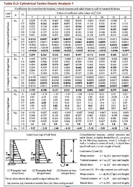
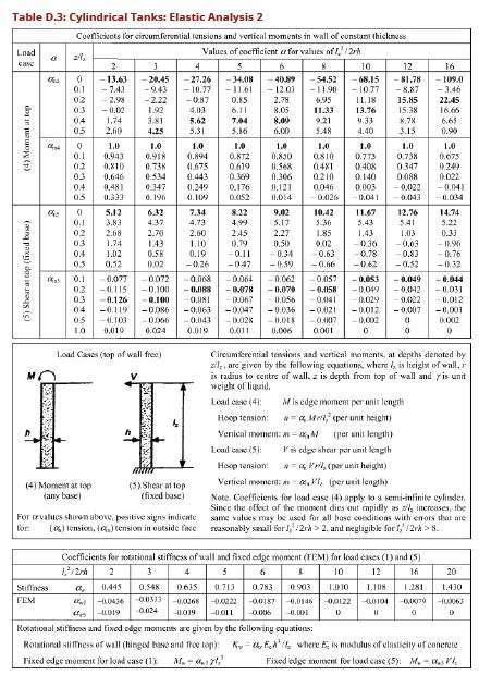
| + | * For walls with free tops and a bottom that is either fixed or hinged values of circumferential tension, vertical moments and radial shear may be calculated from values of coefficients given in Tables D.2 and D.3, | ||
| + | * The design of the tank wall should be by determining the width of the tank wall t and the area of reinforcement required to resist the circumferential tension, shear forces and bending moments determined in the design of slabs, | ||
| + | |||
| + | '''Rectangular Tanks:'''<br> | ||
| + | * In the case of rectangular or polygonal walls, the sides act as two-way slabs, whereby the wall is continued or restrained in the horizontal direction, fixed or hinged at the bottom and hinged or free at the top. The walls thus act as thin plates subjected triangular loading and with boundary conditions varying between full restraint and free edge. | ||
| + | * Analysis for moments and shear forces should be done as that of two-ways slabs considering the walls as individual rectangular slab panels under action | ||
| + | |||
| + | [[Image:AppendixDTableD1.PNG|780px|link=DCOM_Volume_I]]<br> | ||
| + | [[Image:AppendixDTableD1a.PNG|780px|link=DCOM_Volume_I]]<br> | ||
| + | [[Image:AppendixDTableD1b.PNG|780px|link=DCOM_Volume_I]]<br> | ||
| + | of triangularly distributed loads; no need of modification to be applied to | ||
| + | continuous walls provided there is no rotation about the vertical edges, | ||
| + | |||
| + | * In plane walls, the liquid pressure is resisted by both vertical and horizontal bending moments. An estimate should be made of the proportion of the pressure resisted by bending moments in the vertical and horizontal planes. The direct horizontal tension caused by the direct pull due to water pressure on the end walls, should be added to that resulting from horizontal bending moments. | ||
| + | * Magnitudes of moments and shear forces may be calculated using values of constants given in Tables 2.53 for square tanks; in rectangular tanks distribution of the unequal fixity moments at the wall junctions is needed, additional tables 2.78,and 2.79 may be used, When a tank is empty and acted upon by earth loading, consider fixed end condition at the edge of tank wall, | ||
| + | * The design of the tank wall should be by determining the width of the tank wall t and the area of reinforcement required to resist bending moments and shear forces as determined in the design of slabs | ||
| + | * At the vertical edges where the walls of a reservoir are rigidly joined, horizontal reinforcement and haunch bars should be provided to resist the horizontal bending moments even if the walls are designed to withstand the whole load as vertical beams or cantilever without lateral supports | ||
| + | |||
| + | '''Step 1. Establish dimensions'''<br> | ||
| + | Establish the height and diameter/radius of the tank based on the volume:<br> | ||
| + | Diameter,[[Image:AppendixDfomula1.PNG|200px|link=DCOM_Volume_I]] <br> | ||
| + | Where V=Capacity of Water Tank<br> | ||
| + | H= Height of Water Tank<br> | ||
| + | Fb= Free board of the water tank.<br> | ||
| + | |||
| + | '''Step 2. Analysis of forces'''<br> | ||
| + | Sliding joint at base, sliding joint at top slab and resting on firm ground:<br> | ||
| + | There is only one force acting of the wall of the tank is the Hoop Tension, this | ||
| + | should be calculated based from equation: T = γrz<br> | ||
| + | Where:<br> | ||
| + | r is the internal radius of the tank ,<br> | ||
| + | γ is unit weight of the liquid,<br> | ||
| + | z is the depth below the top of tank<br> | ||
| + | |||
| + | '''Rigid joint at base, sliding joint at top slab and resting on firm ground:'''<br> | ||
| + | There are three forces acting on the wall of the tank; Hoop tension, bending | ||
| + | moment and shear force.<br> | ||
| + | |||
| + | Assume tank section wall thickness t;<br> | ||
| + | Calculate the variable H2/2rt, referring to table D.2 read corresponding values of coefficients a<sub>n</sub>, a<sub>m</sub>, a<sub>v</sub>, for calculating hoop tension, bending moment and shear force on the tank wall. | ||
| + | |||
| + | Calculate these forces using equations below: | ||
| + | Hoop Tension, T = a<sub>n</sub> * γ * H * r <br> | ||
| + | Bending Moment, M = a<sub>m</sub> * γ * H<sup>3</sup> <br> | ||
| + | Shear Force, V = a<sub>v</sub> * γ * H<sup>2</sup><br> | ||
| + | |||
| + | Step 3. Calculate area of reinforcement<br> | ||
| + | Sliding joint at base, sliding joint at top slab and resting on firm ground:<br> | ||
| + | Assume a tank section width 1000mm width and section thickness equal to, t:<br> | ||
| + | Check the section compliance to Fire Resistance as per table 3.4 BS 8110;1;1997,<br> | ||
| + | Check concrete cover and grade compliance to durability requirement as per table 3.3 BS 8110; 1; 1997.<br> | ||
| + | Calculate the area of steel from the Hoop tension force only as given by equation;<br> | ||
| + | A<sub>st</sub> =T/σ<sub>st</sub> <br> | ||
| + | |||
| + | Provide reinforcement horizontally spanning at spacing as provided by section | ||
| + | 3.12.11 of BS 8110-1; | ||
| + | |||
| + | Check for section adequacy to resist shear stress; design shear stress , is given | ||
| + | by equation<br> | ||
| + | v =V/b<sub>v</sub>d <br> | ||
| + | Where:<br> | ||
| + | V = Shear Force calculated from above calculation,<br> | ||
| + | v = design shear stress,<br> | ||
| + | bv = breadth of section,<br> | ||
| + | d effective depth.<br> | ||
| + | |||
| + | In no case should v exceed 0.87√fcu or 5N/mm2, where this condition is not | ||
| + | satisfied consider change of width of section or provision of reinforcement. | ||
| + | |||
| + | '''Rigid joint at base, sliding joint at top slab and resting on firm ground:''' | ||
| + | Assume tank section with 1000mm width and section thickness equal to, t; | ||
| + | Check the section compliance to Fire Resistance as per table 3.4 BS 8110;1;1997, | ||
| + | Check concrete cover and grade compliance to durability requirement as per | ||
| + | table 3.3 BS 8110; 1; 1997. | ||
| + | |||
| + | Assume diameter of main bars ɸ, calculate effective depth d, by subtracting the | ||
| + | from the width of section t, the concrete cover and half diameter of bars (ɸ/2);<br> | ||
| + | d = t – cover – ɸ/2 | ||
| + | |||
| + | Check the condition for section moment M, is not greater than ultimate moment | ||
| + | of resistance M<sub>u</sub>, Mu = 0.156fcubd<sup>2</sup> ≥ M is satisfied, if this condition is not satisfied | ||
| + | refer to section 3.4.4.4 of BS 8110-1; 1997 for provision of double reinforcement, | ||
| + | Calculate the area of steel from the following equations: | ||
| + | |||
| + | [[Image:AppendixDfomula2.PNG|533px|link=DCOM_Volume_I]] <br> | ||
| + | |||
| + | Provide reinforcement vertically spanning at spacing as provided by section | ||
| + | 3.12.11 of BS 8110-1; 1997 | ||
| + | |||
| + | Check for section adequacy to resist shear stress, design shear stress , is given | ||
| + | by equation | ||
| + | |||
| + | [[Image:AppendixDfomula3.PNG|800px|link=DCOM_Volume_I]] <br> | ||
| + | In no case should v exceed 0.87√fcu or 5N/mm2, where this condition is not | ||
| + | satisfied consider change of width of section or provision of reinforcement, | ||
| + | |||
| + | Calculate area of steel from the Hoop tension force as given by equation; | ||
| + | [[Image:AppendixDfomula5.PNG|197px|link=DCOM_Volume_I]] <br> | ||
| + | |||
| + | Provide reinforcement horizontally spanning at spacing as provided by section | ||
| + | 3.12.11 of BS 8110-1; 1997, | ||
| + | |||
| + | Where a tank floor slab is resting on firm ground, the weight of water is carried | ||
| + | by the ground. Provide floor slab of minimum thickness about 150mm. Minimum | ||
| + | reinforcement should be provided as per table 3.25 in section 3.12.5.4 BS 8110-1; | ||
| + | 1997. | ||
| + | |||
| + | [[Image:AppendixDfomula2D.JPG|500px|link=DCOM_Volume_I]] <br> | ||
| + | |||
| + | '''Sliding joint at base, sliding joint at top slab and resting on firm ground''':<br> | ||
| + | Assume tank section with 1000mm width and section thickness equal to, t;<br> | ||
| + | Check the section compliance to Fire Resistance as per table 3.4 BS 8110;1;1997,<br> | ||
| + | Check concrete cover and grade compliance to durability requirement as per | ||
| + | table 3.3 BS 8110; 1; 1997. | ||
| + | |||
| + | Calculate the area of steel from the Hoop tension force only as given by equation; | ||
| + | |||
| + | [[Image:AppendixDfomula5.PNG|197px|link=DCOM_Volume_I]] <br> | ||
| + | |||
| + | Provide reinforcement horizontally spanning at spacing as provided by section | ||
| + | 3.12.11 of BS 8110-1;<br> | ||
| + | Check for section adequacy resist shear stress design shear stress , is given by | ||
| + | equation <br> | ||
| + | |||
| + | [[Image:AppendixDfomula3.PNG|800px|link=DCOM_Volume_I]] <br> | ||
| + | |||
| + | In no case should v exceed 0.87√fcu or 5N/mm2, where this condition is not | ||
| + | satisfied consider change of width of section or provision of reinforcement,<br> | ||
| + | Where a tank floor slab is resting on firm ground, the weight of water is carried | ||
| + | by the ground. Provide floor slab of minimum thickness about 150mm. Minimum | ||
| + | reinforcement should be provided as per table 3.25 in section 3.12.5.4 BS 8110-1; | ||
| + | 1997. | ||
| + | |||
| + | [[Image:AppendixDfomula2D.JPG|500px|link=DCOM_Volume_I]] <br> | ||
| + | for steel of strength 460N/mm2, for the case where bearing | ||
| + | pressure of ground cannot support the weight of tank, design of foundation | ||
| + | should be carried out as per BS8110. | ||
| + | |||
| + | '''Joints'''<br> | ||
| + | To avoid the possibility of sympathetic cracking it is important to ensure that | ||
| + | movement joints in the roof correspond with those in the walls, if roof and walls | ||
| + | are monolithic. | ||
| + | However, provision should be made by means of a sliding joint for movement | ||
| + | between the roof and the wall, Correspondence of joints is not so important. | ||
| + | Moreover, in case of tanks intended for the storage of water for domestic | ||
| + | purpose, the roof must be made water-tight. This may be achieved by limiting | ||
| + | the stresses for the rest of the tank, or by the use of the covering by a waterproof | ||
| + | membrane or by providing slopes to ensure adequate drainage. | ||
| + | |||
| + | ==== D.4 Units costs ==== | ||
| + | All standard drawings have been provided with their respective BoQ to enable | ||
| + | accurate establishment of unit costs of the structures. These can be seen on each | ||
| + | of the drawings provided that can be accessed on the MoW Website as Design | ||
| + | Manual (DCOM) link, also can be accessed directly through the address: design. | ||
| + | maji.go.tz | ||
| + | |||
| + | [[Image:TableD2AppendixD.JPG|440px|link=DCOM_Volume_I]] <br> | ||
| + | |||
| + | [[Image:TableD3AppendixD.JPG|440px|link=DCOM_Volume_I]] <br> | ||
| + | |||
| + | Previous Page: [[DCOM_Volume_I_Appendix_C|DCOM_Volume_I_Appendix_C]] << >> Next Page: [[DCOM_Volume_I_Appendix_E|DCOM_Volume_I_Appendix_E]] | ||
Latest revision as of 09:38, 14 June 2021
Contents
1 APPENDIX D: STRUCTURAL DESIGN OF CONCRETE
Concrete members used in water structures range from walls, slabs, roofs and floors. The design of reinforced concrete should ensure these structures have sufficient resistance to cracking, adequate strength and does not allow leakage. Three methods or approaches are available for structural design of concrete, these are described below:
Working Stress Method:
- Produces uneconomical sections,
- Produces stable sections.
Ultimate Load Method:
- Produces cheaper sections,
- Produces unstable sections.
Limit State Method:
- Produces economical sections,
- Produces stable sections.
For the design of water structures it is recommended to use Limit State Design Method, design of structural members should consider two design limits;
Limit of Collapse Design:
- Take care of safety of structure
- Deals with all types of forces, shear force, bending Moment, torsion moment,
- Design criteria refers to the resistance offered by structure which should not be less than the limit value set in design code,
- The appropriate loading value in the structure is based on loading combination of dead loads, live loads, wind load and earth quake load as provided in BS 8110 code.
Limit of serviceability Design:
- Take care of control, deflection, cracking, abrasion and corrosion,
- The calculated values of deflection shall be less than the permissible values of deflection,
1.1 D.1 Design Requirements and Safety Factors
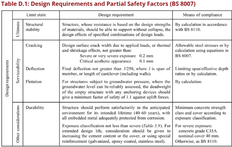
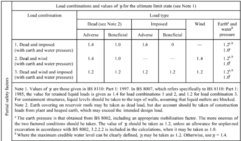
Design requirements for water structures should be according to BS 8110 but modified for the limits state of cracking to take care of crack width under the effect of applied loads, temperature and moisture content. The details of design requirements and partial safety factors are as per BS 8007 shown below.
1.2 D.2 Criteria for Sizing of Concrete Slabs and Walls
Slabs Resting on Firm Ground:
- Concrete slabs casted to rest directly over firm ground should be designed with nominal percentage of reinforcement provided that it is certain that the ground will carry the load without appreciable subsidence in any part.
- Concrete slabs should be cast in panels with sides not more than 4.5 m with contraction or expansion joints between.
- A screed or concrete layer less than 75mm thick should first be placed on the ground and covered with a sliding layer of bitumen paper or other suitable material to destroy the bond between the screed and floor slab.
- In normal circumstances the screed layer should be of grade not weaker than grade 10, where injurious soils or aggressive water are expected, the screed layer should be of grade not weaker than grade 15 and if necessary a sulphate resisting or other special cement should be used.
Slabs Resting on Support:
- When structures are supported on walls or other similar supports the slabs should be designed as floor in buildings for bending moments due to water load and self-weight.
- When the slab is rigidly connected to the walls (as is generally the case) the bending moments at the junction between the walls and slab should be taken into account in the design of slab together with any direct forces transferred to the slab from the walls or from the slab to the wall due to suspension of the slab from the wall.
- If the walls are non-monolithic with the slab, such as in cases, where movement joints have been provided between the slabs and walls, the slab should be designed only for the vertical loads.
- In continuous T-beams and L-beams with ribs on the side remote from the liquid, the tension in concrete on the liquid side at the face of the supports should not exceed the permissible stresses for controlling cracks in concrete. The width of the slab is determined in usual manner for calculation of the resistance to cracking of T-beam, L-beam sections at supports as given in BS8110 design code.
Circular Tanks with sliding joint at base:
- If the wall of a cylindrical tank has a sliding joint at the base and is free at the top, then when the tank is full, no radial shear or vertical bending occurs, the tank wall will be subjected to pure circumferential tension with a varying
magnitude whereby at bottom there is maximum value and at top there is zero value,
- The design of the tank wall should be done by determining the width of the tank wall t and the area of reinforcement Ast required to resist the circumferential tension only,
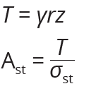
- The varying value of circumferential tension per unit height T at depth z below the top and area of steel required to resist circumferential tension and thickness of wall are given by equations below:
Where:
r is the internal radius of the tank ,
γ is unit weight of the liquid,
z is the depth below the top of tank,
Ast is the area of circumferential tension steel,
σst is the permissible tension strength of steel,
T is circumferential tension (Hoops tension),
Circular Tank with fixed joint at base:
- If the wall of the Tank is supported at the base such that no radial movement occurs; then the wall will be subjected to radial shear, vertical bending and circumferential tension, the value of circumferential tension is always zero at the bottom of the wall,
- The assumption should be made that some portion of the wall at base acts as cantilever and thus some load at bottom are taken by the cantilever effect. Load in the top portion is taken by the hoop tension. The cantilever effect depends on the height of the wall,
- The bottom part of the tank wall about 13 of the tank height H, or 1 meter from bottom whichever is greater is acted upon by a cantilever moment,
- For walls with free tops and a bottom that is either fixed or hinged values of circumferential tension, vertical moments and radial shear may be calculated from values of coefficients given in Tables D.2 and D.3,
- The design of the tank wall should be by determining the width of the tank wall t and the area of reinforcement required to resist the circumferential tension, shear forces and bending moments determined in the design of slabs,
Rectangular Tanks:
- In the case of rectangular or polygonal walls, the sides act as two-way slabs, whereby the wall is continued or restrained in the horizontal direction, fixed or hinged at the bottom and hinged or free at the top. The walls thus act as thin plates subjected triangular loading and with boundary conditions varying between full restraint and free edge.
- Analysis for moments and shear forces should be done as that of two-ways slabs considering the walls as individual rectangular slab panels under action
of triangularly distributed loads; no need of modification to be applied to
continuous walls provided there is no rotation about the vertical edges,
- In plane walls, the liquid pressure is resisted by both vertical and horizontal bending moments. An estimate should be made of the proportion of the pressure resisted by bending moments in the vertical and horizontal planes. The direct horizontal tension caused by the direct pull due to water pressure on the end walls, should be added to that resulting from horizontal bending moments.
- Magnitudes of moments and shear forces may be calculated using values of constants given in Tables 2.53 for square tanks; in rectangular tanks distribution of the unequal fixity moments at the wall junctions is needed, additional tables 2.78,and 2.79 may be used, When a tank is empty and acted upon by earth loading, consider fixed end condition at the edge of tank wall,
- The design of the tank wall should be by determining the width of the tank wall t and the area of reinforcement required to resist bending moments and shear forces as determined in the design of slabs
- At the vertical edges where the walls of a reservoir are rigidly joined, horizontal reinforcement and haunch bars should be provided to resist the horizontal bending moments even if the walls are designed to withstand the whole load as vertical beams or cantilever without lateral supports
Step 1. Establish dimensions
Establish the height and diameter/radius of the tank based on the volume:
Diameter,
Where V=Capacity of Water Tank
H= Height of Water Tank
Fb= Free board of the water tank.
Step 2. Analysis of forces
Sliding joint at base, sliding joint at top slab and resting on firm ground:
There is only one force acting of the wall of the tank is the Hoop Tension, this
should be calculated based from equation: T = γrz
Where:
r is the internal radius of the tank ,
γ is unit weight of the liquid,
z is the depth below the top of tank
Rigid joint at base, sliding joint at top slab and resting on firm ground:
There are three forces acting on the wall of the tank; Hoop tension, bending
moment and shear force.
Assume tank section wall thickness t;
Calculate the variable H2/2rt, referring to table D.2 read corresponding values of coefficients an, am, av, for calculating hoop tension, bending moment and shear force on the tank wall.
Calculate these forces using equations below:
Hoop Tension, T = an * γ * H * r
Bending Moment, M = am * γ * H3
Shear Force, V = av * γ * H2
Step 3. Calculate area of reinforcement
Sliding joint at base, sliding joint at top slab and resting on firm ground:
Assume a tank section width 1000mm width and section thickness equal to, t:
Check the section compliance to Fire Resistance as per table 3.4 BS 8110;1;1997,
Check concrete cover and grade compliance to durability requirement as per table 3.3 BS 8110; 1; 1997.
Calculate the area of steel from the Hoop tension force only as given by equation;
Ast =T/σst
Provide reinforcement horizontally spanning at spacing as provided by section 3.12.11 of BS 8110-1;
Check for section adequacy to resist shear stress; design shear stress , is given
by equation
v =V/bvd
Where:
V = Shear Force calculated from above calculation,
v = design shear stress,
bv = breadth of section,
d effective depth.
In no case should v exceed 0.87√fcu or 5N/mm2, where this condition is not satisfied consider change of width of section or provision of reinforcement.
Rigid joint at base, sliding joint at top slab and resting on firm ground: Assume tank section with 1000mm width and section thickness equal to, t; Check the section compliance to Fire Resistance as per table 3.4 BS 8110;1;1997, Check concrete cover and grade compliance to durability requirement as per table 3.3 BS 8110; 1; 1997.
Assume diameter of main bars ɸ, calculate effective depth d, by subtracting the
from the width of section t, the concrete cover and half diameter of bars (ɸ/2);
d = t – cover – ɸ/2
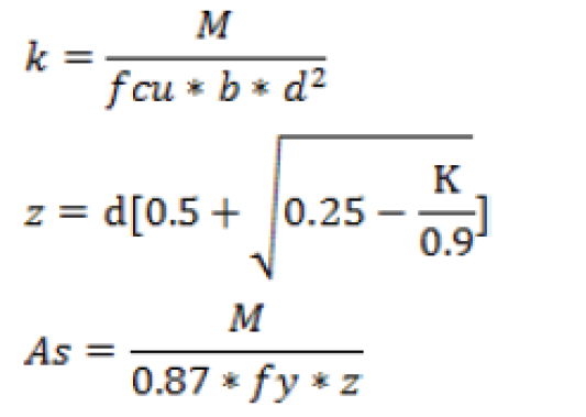
Check the condition for section moment M, is not greater than ultimate moment of resistance Mu, Mu = 0.156fcubd2 ≥ M is satisfied, if this condition is not satisfied refer to section 3.4.4.4 of BS 8110-1; 1997 for provision of double reinforcement, Calculate the area of steel from the following equations:
Provide reinforcement vertically spanning at spacing as provided by section 3.12.11 of BS 8110-1; 1997
Check for section adequacy to resist shear stress, design shear stress , is given by equation
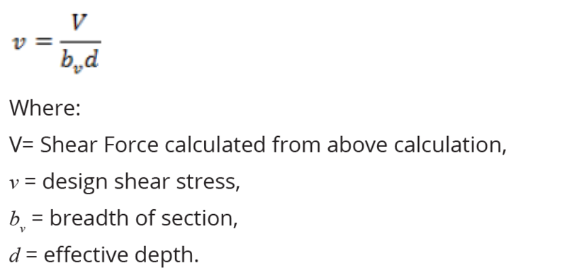
In no case should v exceed 0.87√fcu or 5N/mm2, where this condition is not
satisfied consider change of width of section or provision of reinforcement,
Calculate area of steel from the Hoop tension force as given by equation;

Provide reinforcement horizontally spanning at spacing as provided by section 3.12.11 of BS 8110-1; 1997,
Where a tank floor slab is resting on firm ground, the weight of water is carried by the ground. Provide floor slab of minimum thickness about 150mm. Minimum reinforcement should be provided as per table 3.25 in section 3.12.5.4 BS 8110-1; 1997.
Sliding joint at base, sliding joint at top slab and resting on firm ground:
Assume tank section with 1000mm width and section thickness equal to, t;
Check the section compliance to Fire Resistance as per table 3.4 BS 8110;1;1997,
Check concrete cover and grade compliance to durability requirement as per
table 3.3 BS 8110; 1; 1997.
Calculate the area of steel from the Hoop tension force only as given by equation;
Provide reinforcement horizontally spanning at spacing as provided by section
3.12.11 of BS 8110-1;
Check for section adequacy resist shear stress design shear stress , is given by
equation
In no case should v exceed 0.87√fcu or 5N/mm2, where this condition is not
satisfied consider change of width of section or provision of reinforcement,
Where a tank floor slab is resting on firm ground, the weight of water is carried
by the ground. Provide floor slab of minimum thickness about 150mm. Minimum
reinforcement should be provided as per table 3.25 in section 3.12.5.4 BS 8110-1;
1997.
for steel of strength 460N/mm2, for the case where bearing
pressure of ground cannot support the weight of tank, design of foundation
should be carried out as per BS8110.
Joints
To avoid the possibility of sympathetic cracking it is important to ensure that
movement joints in the roof correspond with those in the walls, if roof and walls
are monolithic.
However, provision should be made by means of a sliding joint for movement
between the roof and the wall, Correspondence of joints is not so important.
Moreover, in case of tanks intended for the storage of water for domestic
purpose, the roof must be made water-tight. This may be achieved by limiting
the stresses for the rest of the tank, or by the use of the covering by a waterproof
membrane or by providing slopes to ensure adequate drainage.
1.2.1 D.4 Units costs
All standard drawings have been provided with their respective BoQ to enable accurate establishment of unit costs of the structures. These can be seen on each of the drawings provided that can be accessed on the MoW Website as Design Manual (DCOM) link, also can be accessed directly through the address: design. maji.go.tz
Previous Page: DCOM_Volume_I_Appendix_C << >> Next Page: DCOM_Volume_I_Appendix_E
