Chapter Nine: Design of Water Structures
Contents
1 Chapter Nine: Design of Water Structures
The main components of a water project include water intakes, break pressure tanks, water points, valve chambers and storage/sedimentation tanks. The following sections describe the design procedures for various water structures.
1.1 SIZING AND LOCATING WATER STRUCTURES
1.1.1 Tanks
1.1.1.1 Storage tanks
The primary purpose of water storage tank is to balance supply during peak hour demand. It is typical to have two peak times during the day, one in the morning the other in the evening when large amounts of water is collected. Water storage tanks should be positioned on higher ground relative to the supply area so as to command pressure.
The following design points should be considered as procedures when estimating the water tank volume/capacity
- Estimate tank capacity by calculating the water demand at various times of the day and comparing that to the yield of the water supply scheme,
- Establish the demand and supply patterns for a typical day during the assessment phase of the project
- The supply yield pattern of the project depends on the design operation period for pumping systems,
- Consider providing tanks for solar-powered projects as they have limited pumping hours,
- Establish the tank volume based on the amount of water needed from the time when there is more water leaving the tank than entering the tank (demand> supply) until the time when there is more water entering the tank than leaving it (Supply > Demand),
- Size the water tank volume so that it is able to meet the deficit during these hours,
- Calculate the volume of the tank by comparing the supply with demand at incremental time periods and balance to the existing storage,
- The balance should start at zero, then calculated for each time period (iteration) by adding the surplus or deficiency to the balance of previous iteration.
This is represented below, with n representing the iteration.
Balance n = Surplus / Deficiency n + Balance n-1
The necessary tank capacity (V tank) is then calculated as the maximum balance (V max) minus the minimum balance (V min) minus the final volume (V final).
V tank= V max – V min –V final (9.2)
Refer to Appendix C example of the sizing of tanks.
1.1.2 Sedimentation/Settling Tanks
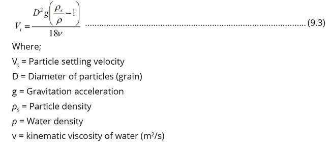
Settling Tanks and clarifiers should be sized based on the settling velocity of the smallest particle to be theoretically 100% removed. Settling velocity of particle may be determined using Stokes law:
Particle characteristics (diameter and density) may be determined in the laboratory through standard methods. Particle settling is governed by the condition that the settling velocity of a particle (Wt) should be less than the settling tank overflow rate (Vo). The settling tank overflow rate (Vo) is defined as:
Overflow rate (Vo) = Flow of water (Q (m3/s)) / (Surface area of settling basin (A)(m2)) (9.4)
Settling tanks and clarifiers may be designed as long rectangles after calculating the surface area, rectangular shapes are hydraulically more stable and easier to control for large volumes. Factors such as flow surges, wind shear, scour, and turbulence may reduce the effectiveness of particle settling. To compensate for these less than ideal conditions, it is recommended to double the area determined from theoretical calculations. It is also important to equalize the water flow distribution at each point across the section of the basin. Poor inlet and outlet designs can produce extremely poor flow characteristics for sedimentation.
Sedimentation efficiency does not depend on the tank depth. If the forward velocity is low enough so that the settled material does not re-suspend from the tank floor, the area is still the main parameter when designing a settling basin or clarifier, taking care that the depth is not too low.
1.1.3 Break Pressure Tanks
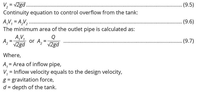
Break pressure tank is a structure that is located between a water reservoir and supply point with the aim of reducing the pressure in the system to zero (atmospheric pressure). Conventional break pressure tank is constructed of concrete in rectangular shape with the depth of the tank about 1.2m. The design criteria for the break pressure tank is to find such that the minimum diameter of the outlet pipe can convey the design flow without causing the overflow in the tank.
Example:
Consider:
Free flow in the tank at depth d conveyed to outlet pipe at velocity V_2:
Choose the dimension of the tank at d values ranging from 1.0 m -1.5 m, length and width of the tank between 1 m to 3 m. The sizing of break pressure tank may be calculated based on the following specifications:
1.1.4 Water Intakes
This is a structure built in the body of water to draw water from the water source. The source may be a canal, river, spring, lake or dam usually built as an integral part of the source. The intake consists of an opening, a strainer or grating through which water enters and conduit conveying the water usually by gravity to a well. These structures are masonry or concrete structures and provide relatively clean water, free from pollution by sand and objectionable floating material.
a) Function of Intakes
The main function of an intake is to provide the highest quality of water from the source and to protect pipes and pumps from being damaged or clogged by wave action, floating objects/debris and submerged marine objects or creatures.
b) Consideration for Locating water intake structures
The following general considerations should be taken while designing and locating water intake structures:
- The source of supply should not have wide fluctuation in water level,
- The site selected should be able to admit water even under lowest flow conditions in the river. Generally, it is preferred that intake should be sufficiently below the shoreline,
- The proximity of the intake structure to the treatment plant,
- Good foundation, away from navigation requirements, safe from effect of floods, storms and scouring in the bottom,
- It should be placed at a location that is free from pollution. It is better to provide the intake at a location reasonably far from settlements so that the water is not contaminated,
- Away from locations with a high frequency of floating materials such as ice, vegetation and logging,
- Intake capacity must be large enough to meet the requirement of design discharge,
- It should not interfere with river traffic if any.
- It should be located where good foundation conditions are available,
- It should be located so that it admits relatively pure water free from mud, sand and pollutants.This implies protection from rapid currents,
- It should be created on the erosion side of a river bend and not the deposition side.
c) Considerations for design of various types of water intakes
(i) Reservoir intake
The water in a reservoir is likely to vary in quality at different levels. This feature makes it usually desirable to take water from about 1 m below the surface. Due to fluctuations in water level, it is desirable to have entry ports at various heights with gate valves. These gate valves are used to regulate water supply. When the water level goes down, a gate valve of a lower port is opened. Access to the ports is through an operating room.
(ii) River intakes
A river intake should consist of a port (conduit) provided with a grating and a sump or gravity well. The conduit should be supported on pillars 1-2 m above the bottom to prevent entry of silt. Also it is kept 1 m below the top surface to avoid entry of floating debris. Velocity should be kept at less than 0.15 m/s to prevent the entry of small fish. River intake structure should be constructed upstream the point of sewage disposal or industrial wastewater disposal. River intakes may need screens to exclude large floating matter. The bottom of the river intake must be sufficiently stable.
(iii) Lake intakes
If the lakeshore is inhabited, the intake should be constructed such as to minimize the danger of pollution. The intake opening should be 2.5 m or more above the bottom so that the entry of silt with water is minimized. The water entry velocity must be low to exclude floating matter, sediment, fish or ice. Entering velocity of 0.15 m/s is usually used. Offshore winds tend to stir up sediments which will be carried for long distances. So, intakes must be located at a distance of not less than 600 meters from the shoreline. Such intakes are recommended to be of multiple level intakes to ensure the source can cope with climate change impacts.
(iv) Intake conduit
Intakes located at long distances from the pumps usually deliver their water to the pump well at the shore end by gravity. This requires a large pipe or conduit so that the velocity is low. But velocity should not be too low to allow for the occurrence of sedimentation. The conduit may be a submerged pipe or tunnel. A submerged pipe should be protected by burying it in a trench, surrounding it with rock or held in place with piling.
1.1.5 Dams
A dam is a structure built across a stream, a river, or an estuary to retain water. Dams are built to provide water for human consumption, for irrigating arid and semiarid lands, or for use in industrial processes.
1.1.5.1 Engineering Classification of Dams
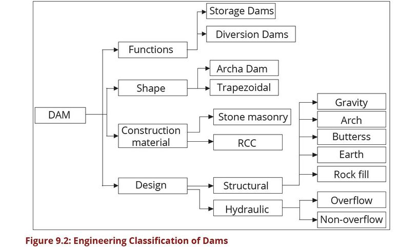
Dams are classified according to their function, shape, construction materials and design. This is termed as engineering classification. Figure 9.2 presents a typical dam engineering classification:
Under structural classification, there are several dam type namely; gravity, arch, buttress, earth fill and rock fill. The Ministry of Water has inventoried about 710 dams whose information has been recorded in a database. As per the inventory, more than 99% of these dams are earth fill and rock fill dams and the rest fall into other categories. Due to this fact, the emphasis of this manual is on earth fill and rock fill dams to guide their design, construction and Operation and Maintenance.
1.1.5.2 Size classification of dams
(a) Large dams
According to International Commission on Large Dams (ICOLD), large dams are
those having capacity of 3million cubic meters or more and a height of more than
5 meter as summarized by the expression below:
5<H<15m and V>3Million cubic meters.
Where:
H is height in meters above riverbed level to maximum crest level,
V is storage volume in million at Maximum Operating Level=Full Supply
Level in most cases.
(b) Small Dams
Small dams have height of less than 2.5m and the product of H2√V and should be
less than 200 as indicated here below:
2.5<H<15m and H2√V <200
Note: (*) Minimum dam height can be changed to 2 or 3 m in the case of dams in
residential or very populated areas.
Also, note: For flood retention dams holding no water the storage volume at crest
of spillway level (design storage volume) should be used.
In Figure 9.3, the ICOLD classification (www.icold-cigb.net) of dams based on size
is presented:


