Difference between revisions of "DCOM Volume I Appendix F"
| Line 100: | Line 100: | ||
V = wind velocity in meters persecond, H = pumping head inmeter,<br> | V = wind velocity in meters persecond, H = pumping head inmeter,<br> | ||
e = wind to water mechanical efficiency, value 0-1. | e = wind to water mechanical efficiency, value 0-1. | ||
| + | |||
| + | [[File:FigureF3.JPG|632px|link=DCOM_Volume_I]] | ||
Windmills with rotor diameters between approximately 2 m to 6 m are usually available. The efficiency, e will rarely exceed 30%.About 5 years of data would give the designer reasonably representative averages following the fact that the monthly wind speed varies greatly between 10 % to 20 % from one year to the next. For successful operation of a wind pump, at least wind speed of 2 to 3 m/s is required. Effort should be made to acquire a wind map of the area to guide with the wind speed throughout the year. This information is available from the Meteorological Department however; it may require interpretation and organization to ensure that it is applicable to the area in question. | Windmills with rotor diameters between approximately 2 m to 6 m are usually available. The efficiency, e will rarely exceed 30%.About 5 years of data would give the designer reasonably representative averages following the fact that the monthly wind speed varies greatly between 10 % to 20 % from one year to the next. For successful operation of a wind pump, at least wind speed of 2 to 3 m/s is required. Effort should be made to acquire a wind map of the area to guide with the wind speed throughout the year. This information is available from the Meteorological Department however; it may require interpretation and organization to ensure that it is applicable to the area in question. | ||
Solar Power<br> | Solar Power<br> | ||
| − | Solar-powered water pumps or photovoltaic pumps (PVP) are an effective alternative to conventional gas or electric pumps. Modern pumps are powered by solar energy effectively and used in different parts of the world. PVP systems offer numerous advantages over water supply system utilizing conventional power (adapted from Water Supply Manual, Uganda 2013): | + | Solar-powered water pumps or photovoltaic pumps (PVP) are an effective |
| + | alternative to conventional gas or electric pumps. Modern pumps are powered | ||
| + | by solar energy effectively and used in different parts of the world. PVP systems | ||
| + | offer numerous advantages over water supply system utilizing conventional | ||
| + | power (adapted from Water Supply Manual, Uganda 2013): | ||
| + | * PVP systems may be the only practical water supply solution in many regions where the logistics make it too expensive or even impossible to supply diesel generators with the required fuel; | ||
| + | * PVP systems are ideal for meeting water requirements for villages between 500 and 2,000 inhabitants and small scale irrigation purposes (up to 3 hectares); | ||
| + | * PVP systems run automatically, require little maintenance and few repairs; | ||
| + | * In areas where PVPs have entered into competition with diesel-driven pumps, their comparatively high initial cost is offset by the achieved savings on fuel and reduced maintenance expenditures; | ||
| + | * The use of solar energy eliminates emissions and fuels pills there by making photo voltaic pumps an environmentally sound and resource-conserving technology; | ||
| + | * There is no need for complicated wiring for the electricity and outside fuel is not needed; | ||
| + | * They can be designed not to require storage batteries, which are expensive and need a lot of maintenance; and | ||
| + | * The maintenance of a PVP system is restricted to regular cleaning of the solar modules. | ||
| − | + | The three components of a solar-powered water pumping system are: | |
| − | |||
| − | |||
| − | |||
| − | |||
| − | |||
| − | |||
| − | |||
Photovoltaic (PV) array (solar cells); Electric motor; and Water pump. | Photovoltaic (PV) array (solar cells); Electric motor; and Water pump. | ||
The PV array generates direct current (DC) electricity when exposed to sunlight. This electricity is fed into the electric motor and which in turn drives the water pump. Optional components of the system include the following: | The PV array generates direct current (DC) electricity when exposed to sunlight. This electricity is fed into the electric motor and which in turn drives the water pump. Optional components of the system include the following: | ||
| − | Controllers (for regulating current and/or voltage); | + | Controllers (for regulating current and/or voltage);<br> |
| − | Inverters (for converting DC power from the PV array to alternating current (AC) power for certain types of motors); | + | Inverters (for converting DC power from the PV array to alternating current (AC) power for certain types of motors);<br> |
| − | Electronic maximum power tracking devices, MPPT(to obtain a more efficient operation of the array and the motor); and | + | Electronic maximum power tracking devices, MPPT(to obtain a more efficient operation of the array and the motor); and<br> |
Batteries (used for both voltage regulation and energy storage and also for generating the required starting currents needed to overcome high electric motor starting torques). | Batteries (used for both voltage regulation and energy storage and also for generating the required starting currents needed to overcome high electric motor starting torques). | ||
| − | + | [[File:FigureF4.JPG|591px|link=DCOM_Volume_I]] | |
| − | |||
| − | |||
| − | |||
The selection of PV arrays and associated equipment should always be made in consultation with the relevant manufacturers. A solar generator provides electricity for driving a submersible electric pump, which in turn pumps water into an elevated water tank that bridges night-time periods and cloudy days. On a clear, sunny day, a medium- size PVP system with an installed power of 2 kW will pump approximately 35 m3 of water per day to a head of 30 meters. That amount of water is sufficient for communities with populations up to 1,400. Today‗s generation of PVP systems is highly reliable. For the most costly part, the PV generator, the manufacturers give a 20 year guarantee on the power output. A crucial prerequisite for the reliability and economic efficiency is that the system be sized appropriate to the local situation. | The selection of PV arrays and associated equipment should always be made in consultation with the relevant manufacturers. A solar generator provides electricity for driving a submersible electric pump, which in turn pumps water into an elevated water tank that bridges night-time periods and cloudy days. On a clear, sunny day, a medium- size PVP system with an installed power of 2 kW will pump approximately 35 m3 of water per day to a head of 30 meters. That amount of water is sufficient for communities with populations up to 1,400. Today‗s generation of PVP systems is highly reliable. For the most costly part, the PV generator, the manufacturers give a 20 year guarantee on the power output. A crucial prerequisite for the reliability and economic efficiency is that the system be sized appropriate to the local situation. | ||
| Line 135: | Line 139: | ||
The formula below can be used to estimate the daily solar power requirement of a water pumping system, in kWh. | The formula below can be used to estimate the daily solar power requirement of a water pumping system, in kWh. | ||
| + | |||
| + | [[File:Fomula332.JPG|649px|link=DCOM_Volume_I]] | ||
| + | |||
| + | In practice, the overall mechanical efficiency of the system is about 30%. A typical | ||
| + | performance curve, showing the power generated by a PV panel during the day | ||
| + | is given in Figure F.5. Solar panels are specified by the Peak Power Rating, the | ||
| + | power output of the PV panel in watts when the panel is receiving radiation of | ||
| + | 1,000 watts per square metre, at ambient temperature of 25 °C. The available | ||
| + | power in watt-hours per day is equal to the hatched area of Figure F.5. This is | ||
| + | area is equal to the Peak Power Rating of the panel multiplied by 5 hours. Thus, | ||
| + | if a panel is rated at 50 Watts Peak Power, then the useful Daily Output is 250 | ||
| + | Watt-hours. | ||
| + | |||
| + | Thus the number of PV panels required can be found using the formula: | ||
| + | |||
| + | [[File:FigureF5.JPG|634px|link=DCOM_Volume_I]] | ||
| + | |||
| + | When designing solar-powered water pumping systems, keep in mind that: | ||
| + | PV arrays panels are prone to vandalism and thus they should be protected by | ||
| + | fencing; and | ||
| + | The shading of PV arrays should be avoided by siting obstructions on the south | ||
| + | side of the arrays and by keeping the surrounding vegetation always cut. | ||
| + | |||
| + | '''Sizing a PVP-System'''<br> | ||
| + | APVP system is sized on the basis of the findings from a local data survey. While | ||
| + | a non-site survey of meteorological and climatic data would be worthwhile it is | ||
| + | usually hindered by lack of time and money. Many systems are based on the | ||
| + | known data of a nearby reference location for which relevant measured values | ||
| + | are available. | ||
| + | |||
| + | If it is possible to visit the intended location, the following field data should be | ||
| + | gathered: | ||
| + | |||
| + | Demand for water in the supply area; | ||
| + | |||
| + | Pumping head with allowance for friction losses and well dynamics; and | ||
| + | Geographical peculiarities. e.g., valley locus. | ||
| + | |||
| + | It is also important to include sociological factors in the planning process. The | ||
| + | future users should be involved in the data-gathering process at the intended | ||
| + | PVP site in order to make early allowance for their customs and traditions in | ||
| + | relation to water. Women in particular must be intensively involved in the | ||
| + | planning, because they are the ones who are usually responsible for maintaining | ||
| + | hygiene and fetching water. Thus, the planning base for each different location | ||
| + | should cover both technical and sociological aspects. | ||
| + | |||
| + | The technical planner can choose from a number of design methods of various | ||
| + | qualities. The most commonly employed approaches are outlined below. | ||
| + | |||
| + | '''Estimation of PV Generator Output'''<br> | ||
| + | To arrive at a first estimate of how much the planned PVP system will cost for | ||
| + | a just selected site, it is a good idea to first estimate the requisite size of the | ||
| + | PV generator. This, however, presumes knowledge of the essential sizing data, | ||
| + | namely the daily water requirement within the area of supply (Vd), the pumping | ||
| + | head to be overcome by the pump (H), and the mean daily total of global | ||
| + | irradiation (Gd) for the design month. A simple arithmetic formula allowing | ||
| + | for the individual system component efficiencies can be used to calculate the | ||
| + | required solar generating power, PSG. The equation reads: | ||
| + | |||
| + | [[File:Fomula334.JPG|634px|link=DCOM_Volume_I]] | ||
| + | |||
| + | According to this equation, it takes a 3.5-kWh PV generator to deliver water at | ||
| + | the rate of 30 m³/d at a head of 50 m for a daily total global irradiation of 5 kWh/ | ||
| + | (m²*d). This gives the planner an instrument for estimating the size of the PV | ||
| + | generator and, hence, the cost of the planned system at the time of site selection. | ||
| + | Installation of the system must be done in accordance with the supplier's manuals | ||
| + | and conditions and the relevant regulations. Relevant qualified personnel must | ||
| + | be consulted at all times. | ||
| + | |||
| + | Recommended use or non-use of solar battery | ||
| + | The solar driven pumping systems can be designed with storage batteries to | ||
| + | make power available when there is solar radiation and when there is no solar | ||
| + | radiation. The capital cost of a solar pump with power storage batteries is high | ||
| + | while also its maintenance costs are also high. It is advisable that for water | ||
| + | pumping installation of a large enough overhead reservoirs can allow a solar | ||
| + | pump to store the required daily water so that when solar radiation is low the | ||
| + | storage tank can continue to supply the needed water. However, in areas of poor | ||
| + | security it may be worth to include a small battery to run the security lights during | ||
| + | dark hours of the day. | ||
| + | |||
| + | Examples on pump calculations is provided below. | ||
| + | |||
| + | [[File:TableF1.JPG|644px|link=DCOM_Volume_I]] | ||
| + | |||
| + | '''Example F.1: Sizing the pump from the desired flow rate'''<br> | ||
| + | Same Mwanga Korogwe (SMK) projects aims to provide a total of 456,931 | ||
| + | residents in the first phase, where, according to design manual, 250 residents | ||
| + | are enough to be served by one water tap. Water requirement is 75 liters/p/day | ||
| + | in urban areas. Estimate the flowrate that must be supplied by pumping<br> | ||
| + | The total demand for water for residents is 34,269,825 liters per day.<br> | ||
| + | Allow for 20% losses<br> | ||
| + | Thus the total demand is 34,269,825 + 20% x 34269825 = 41,123,790 liters per | ||
| + | day<br> | ||
| + | Assume a peak factor of 1.2 The total daily requirement becomes 41,123.79 * 1.2 | ||
| + | = 49,348,548 liters per day<br> | ||
| + | Hourly requirement in m3/h:<br> | ||
| + | [[File:Qfomula2.JPG|644px|link=DCOM_Volume_I]] | ||
| + | |||
| + | So the pumping plant (pump) should have at least 2,056.2 m3/h.<br> | ||
| + | With the intention of increasing efficiency we can put two pumps with a capacity | ||
| + | of 1,028.09475 m3/ h for each pump and a plant (pump) one standby.<br> | ||
| + | [[File:Req.JPG|644px|link=DCOM_Volume_I]] | ||
| + | |||
| + | '''Total head loss'''<br> | ||
| + | This is pressure required to be overcome, sum of all opposition to the flow of | ||
| + | water from the source to the destination tank or customer tap. Includes height | ||
| + | required to be overcame pumped water, frictions inside pipes due to bends and | ||
| + | actual water loss in joints. Therefore it is found from hydraulic calculations. | ||
| + | |||
| + | '''Horsepower –kW'''<br> | ||
| + | Source games (intake)<br> | ||
| + | Head from the source until the plant is 50 m<br> | ||
| + | Power pump (Power) = Energy (Time) Energy (Time)<br> | ||
| + | |||
| + | [[File:Pumps.JPG|644px|link=DCOM_Volume_I]] | ||
| + | |||
| + | '''Example F.2: Solar System Design'''<br> | ||
| + | If a PV pump for water supply is to be installed in a village of 625 populations, | ||
| + | then water is to be pumped from the height of 15 m. The water then has to be | ||
| + | pumped to the storage tank that is at a height of 15 m. Dynamic head of the | ||
| + | system is approximately 7 m (frictional losses of lifting water to the storage tank | ||
| + | are included). | ||
| + | |||
| + | [[File:TWH.JPG|634px|link=DCOM_Volume_I]] | ||
| + | |||
| + | '''System size''' for drinking water supply would also include the number of days | ||
| + | the water has to be stored, two to three days of water storage is to be accounted | ||
| + | for the designing the system. However the first step is to determine total energy | ||
| + | required to lift the water. Although there is no charge controller.<br> | ||
| + | |||
| + | Note: There is no charge controller or battery involved in the system, certain | ||
| + | conversion losses at the time of water pumping occur. | ||
| + | |||
| + | [[File:Say18.JPG|634px|link=DCOM_Volume_I]] | ||
Previous Page: [[DCOM_Volume_I_Appendix_E|DCOM_Volume_I_Appendix_E]] << >> Next Page: [[DCOM_Volume_I_Appendix_G|DCOM_Volume_I_Appendix_G]] | Previous Page: [[DCOM_Volume_I_Appendix_E|DCOM_Volume_I_Appendix_E]] << >> Next Page: [[DCOM_Volume_I_Appendix_G|DCOM_Volume_I_Appendix_G]] | ||
Latest revision as of 16:10, 14 June 2021
APPENDIX F: SOURCE OF PUMPING POWER
General
The different types of power sources commonly used for water supply pumps include:
- Grid power,
- Diesel/gasoline generators and engines,
- Natural gas/biogas generators,
- Solar energy,
- Wind energy.
The choice of water pumping energy depends on several factors namely:
- Availability of and proximity to grid power,
- Capital costs of the alternatives,
- Operational costs of the alternatives.
In Tanzania when deciding on the water pumping energy, grid power is considered as the basic source in the sense that when available it becomes the 1st choice. It is only when the grid source is too far from the pumping point that the other sources are considered. The three alternatives to grid power namely diesel/petrol/natural gas/biogas generators or engines have both positives and negatives. In the following subchapters each alternative shall be discussed.
Grid power
National grid connection enables a water pumping station to remain connected
to the larger, wide-area electrical grid. The electrical grid is responsible for
generating, distributing and balancing electricity across a wide area. Since most
of the national electric power supply is mainly from hydropower plants (64% of
the total generated electricity in 2016) (Aly, Moner-Girona et al. 2019),and natural
gas the price is stable and the costs of power generation cheaper than the other
sources except solar energy. Grid power is the most stable and trustable source
of water pumping power (Although other renewable sources can also be made
stable and trustable). It is also the cheapest in terms of capital cost since electric
motors are cheaper than other forms of prime movers such as generators which
also require engines in addition to electric motor for the pumps.
PV systems require higher investment costs due to the large area of PV required (It should however be noted that the costs of PV is getting lower). Similarly the running costs for electric motors is cheaper than that of engines except those utilizing own generated fuel such and gas or biogas fuel. In terms of running costs solar PV is the cheapest. Most of water supply sources requiring pumping are situated in rural areas where grid power may not be available. When deciding the alternatives the designers have to compare the costs of bringing grid power from the nearest point to the site against the capital costs of the other energy sources.
Diesel Generators/Diesel Engines
There are two approaches applied when considering engines for water pumping.
An engine may directly be coupled with the pump running on diesel or petrol.
Most small irrigation pumps are of this type. The other way is a diesel run
generator which provides electricity for running the pump. Here a normal electric
driven pump is supplied with power from the generator instead of grid. Diesel
run generators of different sizes (20 kW to over 3,000 kW) are available in the
market to suit power requirements for various applications.
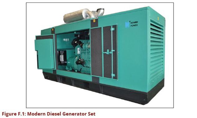
Designers of water supply systems would need to estimate the power requirement for pumping and distribution of water in order to be able to order the right size of a generator. Properly sized generator sets are easy to install. The running costs are high due to the requirement of fuel (Diesel/petrol) and the maintenance of the engine.
Gas/biogas Generators
There are also generators which run on natural gas or biogas in case this type of
fuel is readily available. Natural gas is locally available in some areas of Tanzania
and already there are plans to introduce natural gas run automobiles. Biogas
on the other hand can be produced locally in a bio-digester from industrial/
bio wastes containing high loading of organic matter. These two gases provide
cheaper source of fuel for generating power. Note that when procuring gas
engines one has to be specific whether the generator shall use biogas or natural
gas. Natural gas and biogas are slightly different in terms of composition.
Wind Driven Pump
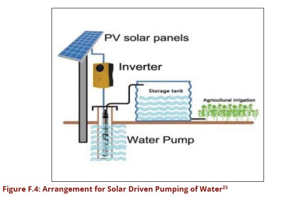
The amount of water a wind-powered water pumping system can deliver depends on the speed and duration of the wind, the size and efficiency of the rotor, the efficiency of the pump being used, and how far the water has to be lifted. The power delivered by a windmill can be determined from the following equation:
P=0.0109D2V3e
Where: P is power in watts, D is the rotor diameter in metres, V is the wind speed in kilometres per hour, and e is the efficiency of the wind turbine. As can be seen from this expression, relatively large increases in power result from comparatively small increases in the size of the rotor and the available wind speed; doubling the size of the rotor will result in a four-fold increase in power, while doubling the wind speed will result in an eight-fold increase in power
However, the efficiency of wind turbines decreases significantly in both low and high winds, so the result is that most commercially-available windmills operate best in a range of wind-speeds between about 15 km/hr and 50 km/hr.
For adequate usage of wind power, the wind speed should be higher than 2.5 to 3 m/s for at least 60% of the time. The windmill should be placed above surrounding obstructions such as trees or buildings within 125 m; preferably, the windmill should be set out on a tower of 4.5 to 6 m high. Consider protection by provision of an automatic lubrication system or covering of the windmill driving mechanism. In order to directly pump water by a windmill, there is the need to match the characteristics of the local wind regime, the windmill and the pump. This therefore means that, the manufacturers should always be consulted regarding the selection of the equipment. The discharge, Q that can be pumped by a windmill can be estimated by the formula below:
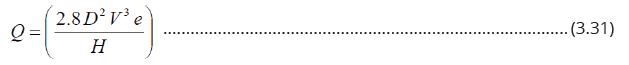
Where,
Q = Discharge in litres per minute (l/min),
D = wind rotor diameter in meters,
V = wind velocity in meters persecond, H = pumping head inmeter,
e = wind to water mechanical efficiency, value 0-1.
Windmills with rotor diameters between approximately 2 m to 6 m are usually available. The efficiency, e will rarely exceed 30%.About 5 years of data would give the designer reasonably representative averages following the fact that the monthly wind speed varies greatly between 10 % to 20 % from one year to the next. For successful operation of a wind pump, at least wind speed of 2 to 3 m/s is required. Effort should be made to acquire a wind map of the area to guide with the wind speed throughout the year. This information is available from the Meteorological Department however; it may require interpretation and organization to ensure that it is applicable to the area in question.
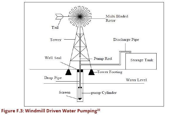
Solar Power
Solar-powered water pumps or photovoltaic pumps (PVP) are an effective
alternative to conventional gas or electric pumps. Modern pumps are powered
by solar energy effectively and used in different parts of the world. PVP systems
offer numerous advantages over water supply system utilizing conventional
power (adapted from Water Supply Manual, Uganda 2013):
- PVP systems may be the only practical water supply solution in many regions where the logistics make it too expensive or even impossible to supply diesel generators with the required fuel;
- PVP systems are ideal for meeting water requirements for villages between 500 and 2,000 inhabitants and small scale irrigation purposes (up to 3 hectares);
- PVP systems run automatically, require little maintenance and few repairs;
- In areas where PVPs have entered into competition with diesel-driven pumps, their comparatively high initial cost is offset by the achieved savings on fuel and reduced maintenance expenditures;
- The use of solar energy eliminates emissions and fuels pills there by making photo voltaic pumps an environmentally sound and resource-conserving technology;
- There is no need for complicated wiring for the electricity and outside fuel is not needed;
- They can be designed not to require storage batteries, which are expensive and need a lot of maintenance; and
- The maintenance of a PVP system is restricted to regular cleaning of the solar modules.
The three components of a solar-powered water pumping system are: Photovoltaic (PV) array (solar cells); Electric motor; and Water pump.
The PV array generates direct current (DC) electricity when exposed to sunlight. This electricity is fed into the electric motor and which in turn drives the water pump. Optional components of the system include the following:
Controllers (for regulating current and/or voltage);
Inverters (for converting DC power from the PV array to alternating current (AC) power for certain types of motors);
Electronic maximum power tracking devices, MPPT(to obtain a more efficient operation of the array and the motor); and
Batteries (used for both voltage regulation and energy storage and also for generating the required starting currents needed to overcome high electric motor starting torques).
The selection of PV arrays and associated equipment should always be made in consultation with the relevant manufacturers. A solar generator provides electricity for driving a submersible electric pump, which in turn pumps water into an elevated water tank that bridges night-time periods and cloudy days. On a clear, sunny day, a medium- size PVP system with an installed power of 2 kW will pump approximately 35 m3 of water per day to a head of 30 meters. That amount of water is sufficient for communities with populations up to 1,400. Today‗s generation of PVP systems is highly reliable. For the most costly part, the PV generator, the manufacturers give a 20 year guarantee on the power output. A crucial prerequisite for the reliability and economic efficiency is that the system be sized appropriate to the local situation.
The power output of a PV array is directly proportional to the solar irradiation falling on to the array. The power flow through a typical solar-powered water pumping system is in Figure 3.23. Accordingly, the best efficiencies that are expected are as follows:
PV array -11% of the total solar power received by the PV array; and Motor-pump unit - 4.5% of the total power received by the PV array
The formula below can be used to estimate the daily solar power requirement of a water pumping system, in kWh.
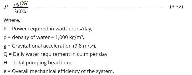
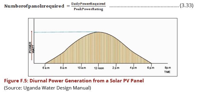
In practice, the overall mechanical efficiency of the system is about 30%. A typical performance curve, showing the power generated by a PV panel during the day is given in Figure F.5. Solar panels are specified by the Peak Power Rating, the power output of the PV panel in watts when the panel is receiving radiation of 1,000 watts per square metre, at ambient temperature of 25 °C. The available power in watt-hours per day is equal to the hatched area of Figure F.5. This is area is equal to the Peak Power Rating of the panel multiplied by 5 hours. Thus, if a panel is rated at 50 Watts Peak Power, then the useful Daily Output is 250 Watt-hours.
Thus the number of PV panels required can be found using the formula:
When designing solar-powered water pumping systems, keep in mind that: PV arrays panels are prone to vandalism and thus they should be protected by fencing; and The shading of PV arrays should be avoided by siting obstructions on the south side of the arrays and by keeping the surrounding vegetation always cut.
Sizing a PVP-System
APVP system is sized on the basis of the findings from a local data survey. While
a non-site survey of meteorological and climatic data would be worthwhile it is
usually hindered by lack of time and money. Many systems are based on the
known data of a nearby reference location for which relevant measured values
are available.
If it is possible to visit the intended location, the following field data should be gathered:
Demand for water in the supply area;
Pumping head with allowance for friction losses and well dynamics; and Geographical peculiarities. e.g., valley locus.
It is also important to include sociological factors in the planning process. The future users should be involved in the data-gathering process at the intended PVP site in order to make early allowance for their customs and traditions in relation to water. Women in particular must be intensively involved in the planning, because they are the ones who are usually responsible for maintaining hygiene and fetching water. Thus, the planning base for each different location should cover both technical and sociological aspects.
The technical planner can choose from a number of design methods of various qualities. The most commonly employed approaches are outlined below.
Estimation of PV Generator Output
To arrive at a first estimate of how much the planned PVP system will cost for
a just selected site, it is a good idea to first estimate the requisite size of the
PV generator. This, however, presumes knowledge of the essential sizing data,
namely the daily water requirement within the area of supply (Vd), the pumping
head to be overcome by the pump (H), and the mean daily total of global
irradiation (Gd) for the design month. A simple arithmetic formula allowing
for the individual system component efficiencies can be used to calculate the
required solar generating power, PSG. The equation reads:

According to this equation, it takes a 3.5-kWh PV generator to deliver water at the rate of 30 m³/d at a head of 50 m for a daily total global irradiation of 5 kWh/ (m²*d). This gives the planner an instrument for estimating the size of the PV generator and, hence, the cost of the planned system at the time of site selection. Installation of the system must be done in accordance with the supplier's manuals and conditions and the relevant regulations. Relevant qualified personnel must be consulted at all times.
Recommended use or non-use of solar battery The solar driven pumping systems can be designed with storage batteries to make power available when there is solar radiation and when there is no solar radiation. The capital cost of a solar pump with power storage batteries is high while also its maintenance costs are also high. It is advisable that for water pumping installation of a large enough overhead reservoirs can allow a solar pump to store the required daily water so that when solar radiation is low the storage tank can continue to supply the needed water. However, in areas of poor security it may be worth to include a small battery to run the security lights during dark hours of the day.
Examples on pump calculations is provided below.

Example F.1: Sizing the pump from the desired flow rate
Same Mwanga Korogwe (SMK) projects aims to provide a total of 456,931
residents in the first phase, where, according to design manual, 250 residents
are enough to be served by one water tap. Water requirement is 75 liters/p/day
in urban areas. Estimate the flowrate that must be supplied by pumping
The total demand for water for residents is 34,269,825 liters per day.
Allow for 20% losses
Thus the total demand is 34,269,825 + 20% x 34269825 = 41,123,790 liters per
day
Assume a peak factor of 1.2 The total daily requirement becomes 41,123.79 * 1.2
= 49,348,548 liters per day
Hourly requirement in m3/h:
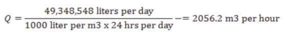
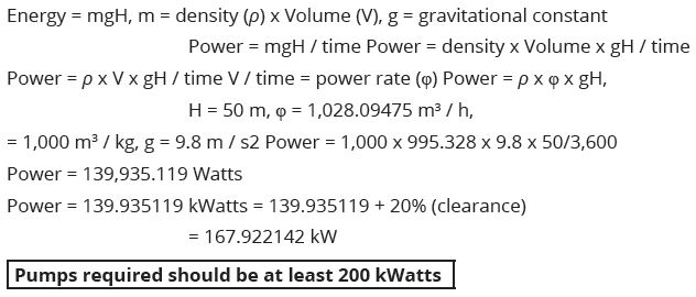
So the pumping plant (pump) should have at least 2,056.2 m3/h.
With the intention of increasing efficiency we can put two pumps with a capacity
of 1,028.09475 m3/ h for each pump and a plant (pump) one standby.

Total head loss
This is pressure required to be overcome, sum of all opposition to the flow of
water from the source to the destination tank or customer tap. Includes height
required to be overcame pumped water, frictions inside pipes due to bends and
actual water loss in joints. Therefore it is found from hydraulic calculations.
Horsepower –kW
Source games (intake)
Head from the source until the plant is 50 m
Power pump (Power) = Energy (Time) Energy (Time)
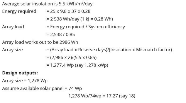
Example F.2: Solar System Design
If a PV pump for water supply is to be installed in a village of 625 populations,
then water is to be pumped from the height of 15 m. The water then has to be
pumped to the storage tank that is at a height of 15 m. Dynamic head of the
system is approximately 7 m (frictional losses of lifting water to the storage tank
are included).
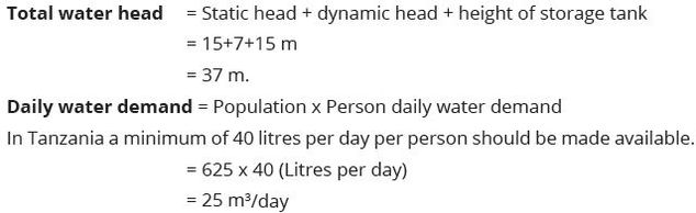
System size for drinking water supply would also include the number of days
the water has to be stored, two to three days of water storage is to be accounted
for the designing the system. However the first step is to determine total energy
required to lift the water. Although there is no charge controller.
Note: There is no charge controller or battery involved in the system, certain conversion losses at the time of water pumping occur.
Previous Page: DCOM_Volume_I_Appendix_E << >> Next Page: DCOM_Volume_I_Appendix_G